
LED display screen signal interconnection method

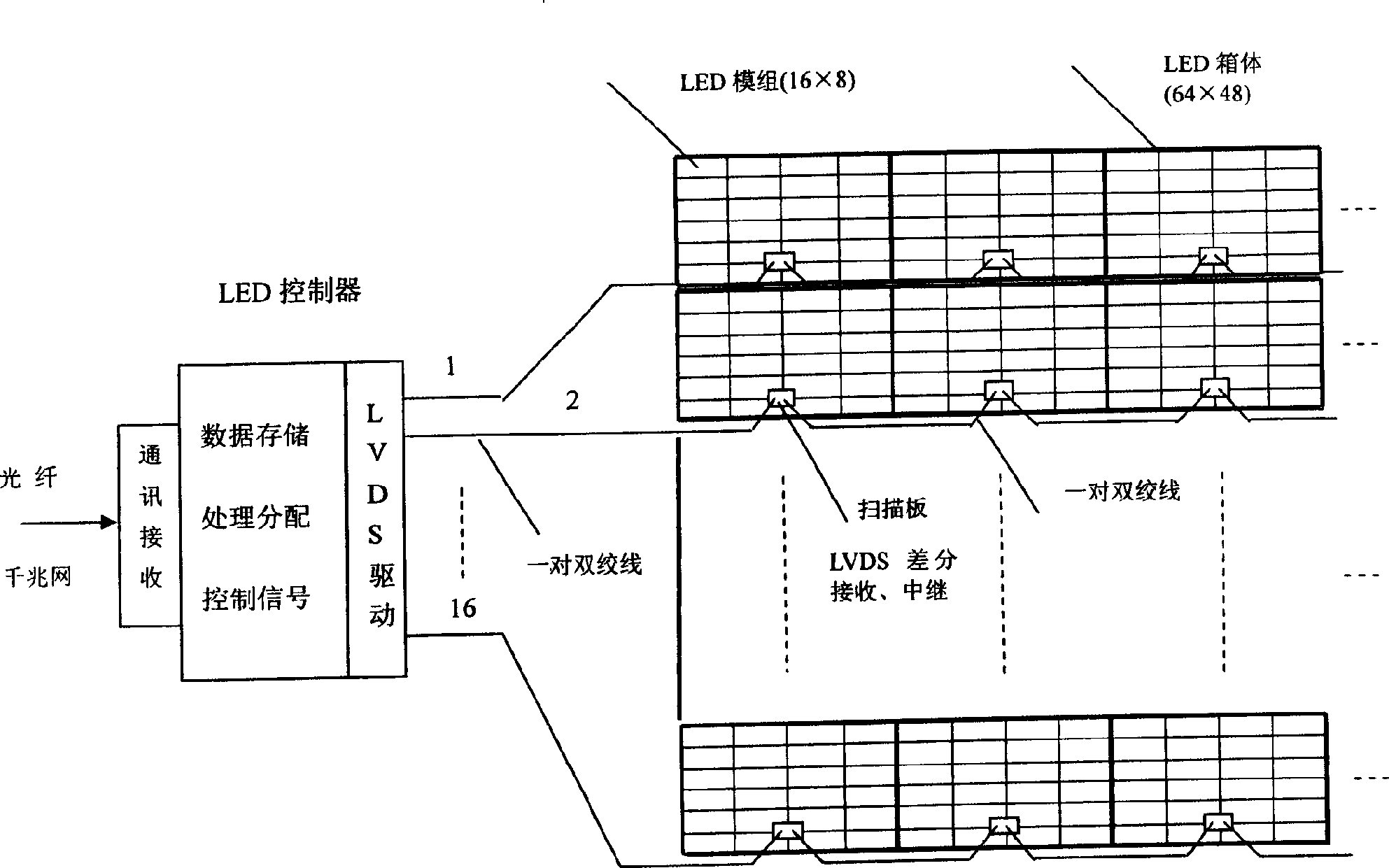
A LED display and signal technology, applied to static indicators, instruments, etc., can solve the problems of unsatisfactory requirements, low transmission frequency, and many wires, and achieve transmission stability, high-efficiency signal interconnection, and simplified connection structure. Effect

Active Publication Date: 2006-02-15
KONKA GROUP
View PDF0 Cites 16 Cited by
  • Summary
  • Abstract
  • Description
  • Claims
  • Application Information

AI Technical Summary

Problems solved by technology

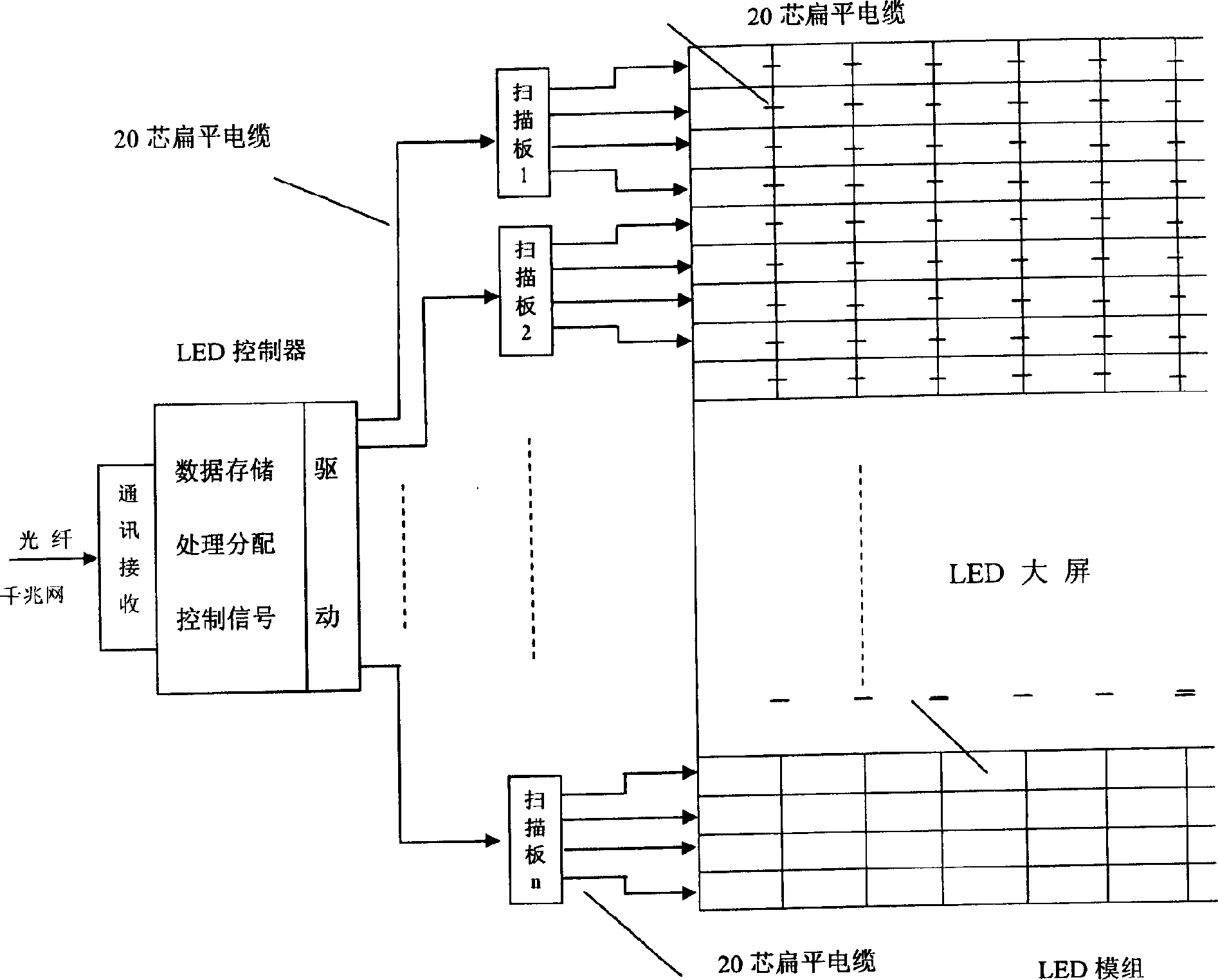
[0005] The disadvantage of this method in the prior art is that there are many wires. For example, the connection between the LED control panel and each display partition can reach hundreds of wires, the transmission frequency is low (<5MHz), the transmission distance is short, and it is easy to be interfered. Distortion is prone to occur, such as narrowing of pulse width, causing signal asynchronous screen flickering or chromatic aberration before and after, etc.
This method can be used in monochrome or four-color screens, but in high-quality full-color LED screens, it can no longer meet the requirements in terms of bandwidth, speed and anti-interference issues.
In order to meet the requirements such as speed, the LED display controller and the box, and between the box and the box also use copper axis cables and optical fiber transmission methods, but the technology and structure adopted by these two transmission methods are more complicated, and the cost is high. Higher and less convenient to install
[0006] In the traditional design, the transmission of data and control signals between the LED controller and the display partition, and between the cabinet and the cabinet adopts the direct bus drive and the connection mode of the flat cable, so the transmission frequency is low and the signal is easy to occur. Distortion and more lines are used, resulting in a more complex structure and poor signal quality

Method used


Image

  • LED display screen signal interconnection method
  • LED display screen signal interconnection method
  • LED display screen signal interconnection method

Examples


Embodiment Construction

[0028] Various preferred embodiments of the present invention will be described in detail below in conjunction with the accompanying drawings.

[0029] LVDS (Low Voltage Differential Signaling, Low Voltage Differential Signaling) is a small amplitude differential signal technology that uses very low amplitude signals (100mv-450mv) to transmit data through a pair of parallel PCB traces or balanced cables. This transmission standard adopts a constant current two-wire differential drive mode, which has strong anti-common-mode noise interference capability, low electromagnetic radiation, no ringing and peak signals caused by signal switching, and has good EMI (electromagnetic interference) characteristics. It also has the advantages of fast data reversal and low power consumption. Using this technology, as long as the length of parallel transmission lines is consistent enough, and good impedance matching is provided at the receiving end to reduce signal reflection, a pair of lines...


PUM


Abstract

The invention discloses an interconnecting method of LED display screen signal, which consists of LED display screen controller and several boxes of bus groups and comprises the following steps: a) the LED display screen controller cascades each leading-end bus of bus groups by twisted-pair line; b) several boxes of each box group cascade by twisted-pair line.

Description

technical field [0001] The invention belongs to the technical field of LED display screen control, in particular to a signal interconnection method between LED display screen boxes. Background technique [0002] Known LED display screens generally display digital video images in partitions. For example, for an LED display screen with a resolution of 1024×768 pixels, horizontal segmentation technology is generally used indoors, and it is divided into 48 rows of display partitions with 1024×16 pixels, and each row of display partitions is composed of 16 display modules with 64×16 pixels. Group composition; outdoor LED display screens generally adopt box segmentation technology, which can be divided into 16 x 16 box-style distribution display partitions according to 64 x 48 pixels, and each display partition is composed of 24 display modules with 16 x 8 pixels. . Each display partition of the two partition methods is equipped with a signal scanning board, which is responsible...

Claims


Application Information

Patent Timeline
Patent Type & Authority Applications(China)
IPC IPC(8): G09G3/32
Inventor 魏洵佳任平梁宁朱宏
Owner KONKA GROUP
Learn More