Tubular reactor for carrying out catalytic gas-phase reactions and method for operating said reactor

A casing reactor and phase reaction technology, applied to chemical instruments and methods, methods for chemically changing substances by using atmospheric pressure, chemical/physical/physicochemical nozzle reactors, etc., can solve the problem of explosive load, Unbearable, explosion hazards increase the pressure-resistant glass plate and other problems, to achieve and accelerate the starting process and facilitate the starting process

Inactive Publication Date: 2006-02-22
MAN ENERGY SOLUTIONS SA
View PDF4 Cites 10 Cited by
  • Summary
  • Abstract
  • Description
  • Claims
  • Application Information

AI Technical Summary

Problems solved by technology

[0004] 2) In addition to the load, the risk of explosion increases with the length of time the two components stay together
Pressure-resistant glass panels are not sufficient due to the increased risk of explosion if it is desired to further increase the loading capacity and output in this way
Replacing the - already expensive - pressure glass panel after an explosion requires tedious repair work and corresponding downtime
The bursting of the pressure glass causes a pressure wave to be transmitted outwards, the sound of which can be heard for kilometers away and is therefore already quite unbearable

Method used


Image

  • Tubular reactor for carrying out catalytic gas-phase reactions and method for operating said reactor
  • Tubular reactor for carrying out catalytic gas-phase reactions and method for operating said reactor
  • Tubular reactor for carrying out catalytic gas-phase reactions and method for operating said reactor

Examples


Embodiment Construction

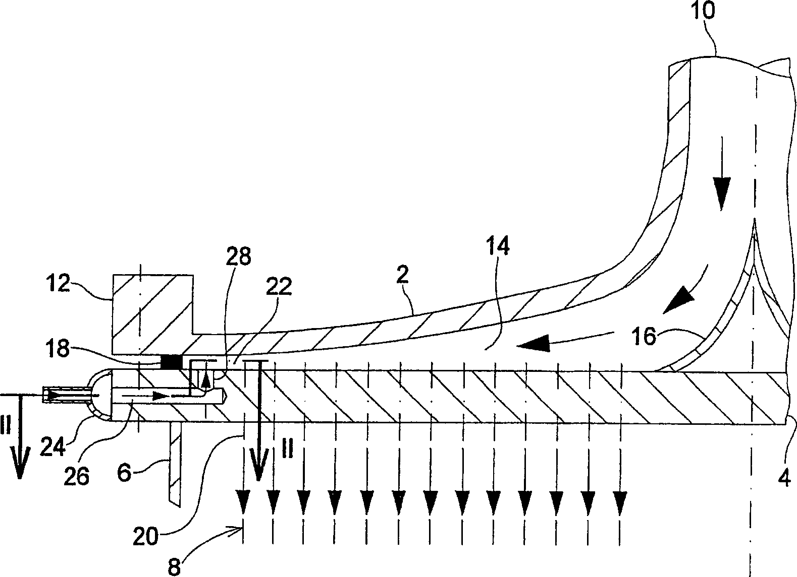
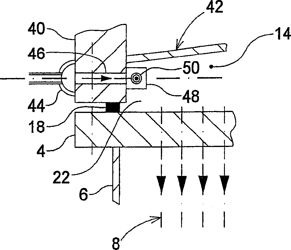
[0025] figure 1 Slightly schematically shows the gas inlet side of a jacketed reactor according to the invention for carrying out catalytic gas phase reactions in areas with a risk of explosion or even deflagration. exactly in figure 1 Can see a specially designed gas inlet mouth 2, be positioned at the tube bottom 4 below it, be connected to the reactor jacket 6 above this tube bottom, an annular contact tube bundle 8 and a gas inlet The gas inlet pipe joint 10 of the mask 2. A tube bundle, usually containing a suitable catalyst filling, flows within the reactor jacket 6 by a heat transfer medium, which is in any case liquid during operation, by means of which a suitable temperature distribution is maintained along the contact tubes and excess heat of reaction.

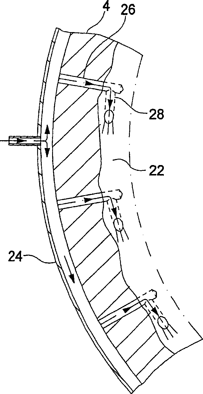
[0026] as by figure 1 It can also be seen that, except for a solid and detailed bead 12 for the installation and sealing of the gas inlet mouthpiece on the bottom of the tube 4, the gas inlet mouthpiece 2 is desi...


PUM


Abstract

The invention relates to a tubular reactor for carrying out catalytic gas-phase reactions, containing a catalyst tube bundle (8) that is traversed by the relevant reaction gas mixture, is filled with a catalyst, extends between two tube sheets (4, 148) and around which flows a heat transfer medium contained within a surrounding reactor jacket (6). Said reactor also comprises gas entry and discharge hoods (2; 60) that cover the two tube sheets for supplying the relevant process gas to the catalyst tubes and for discharging the reacted process gas from the catalyst tubes. The reactor is characterised in that together with all the parts that come into contact with the process gas mixture, it is designed to have an appropriate strength for withstanding the deflagration and explosive pressures that are to be taken into account during its operation. The volume available to the process gas mixture prior to its entry into the catalyst tubes is restricted as much as possible in construction and flow engineering terms. The inventive reactor permits a higher charge of an explosion-critical component to be added to the process gas that is to be treated in a risk-free, economical manner and an explosion-critical range in the current gas composition to be traversed during the start-up phase of the reactor.

Description

technical field [0001] The invention relates to a jacketed reactor according to the preamble of claim 1 and to a method for operating such a reactor. Background technique [0002] A jacketed reactor of this type is known, for example, from DE 10021986.1. In this particular case, however, in order to reduce the risk of explosion, the explosively hazardous components of the reaction gas to be reacted in the reactor are added in part only immediately before or while entering the reaction tube. Furthermore, the components are kept in a small volume before entering, for example by means of an interior component in the usually more or less hemispherical gas inlet opening. These measures are based on the recognition that: [0003] 1) In order to obtain as high a production efficiency as possible in relation to the size of the reactor plant, it is desirable that the loading of reaction gases with explosive components, such as oxygen and hydrocarbons, be made as large as possible. ...

Claims


Application Information

Patent Timeline
Patent Type & Authority Applications(China)
IPC IPC(8): B01J8/06B01J19/00B01J3/02B01J3/03B01J3/04B01J8/00B01J19/26C07C51/21F28D7/16F28F9/02F28F27/02
CPCB01J3/042B01J19/0053B01J8/065B01J2208/00212B01J8/067B01J2208/00716B01J2219/00265B01J3/03F28F9/0229B01J2219/00263C07C51/21B01J2208/00203B01J8/0085B01J2208/00849B01J4/002B01J19/002F28D7/16B01J3/02F28F2225/08B01J8/008B01J19/26B01J2208/00548F28F9/0265B01J2208/0053B01J2208/00495Y10T137/043Y10T137/1654
Inventor F·盖特乌贝尔M·莱尔
Owner MAN ENERGY SOLUTIONS SA
Why Eureka
Try Eureka