Metal grating template making process

A metal grating and metal workpiece technology, which is applied in the field of metal grating stencil production, can solve the problems of low etching pattern precision, poor etching surface finish, slow etching rate, etc. The effect of high graphic precision and large etching depth

Inactive Publication Date: 2006-03-01
INST OF OPTICS & ELECTRONICS - CHINESE ACAD OF SCI
View PDF0 Cites 12 Cited by
  • Summary
  • Abstract
  • Description
  • Claims
  • Application Information

AI Technical Summary

Problems solved by technology

Wet etching is to use chemical etching solution for etching. The method and equipment are simple, but there is a serious undercutting effect, and the accuracy of the etching pattern is not high.
Reactive ion etching is generally used for dry etching, which has good directionality and can etch fine patterns, but there are problems such as complex equipment, high cost, slow etching rate, and poor etching surface finish.

Method used


Image

  • Metal grating template making process
  • Metal grating template making process

Examples


Embodiment Construction

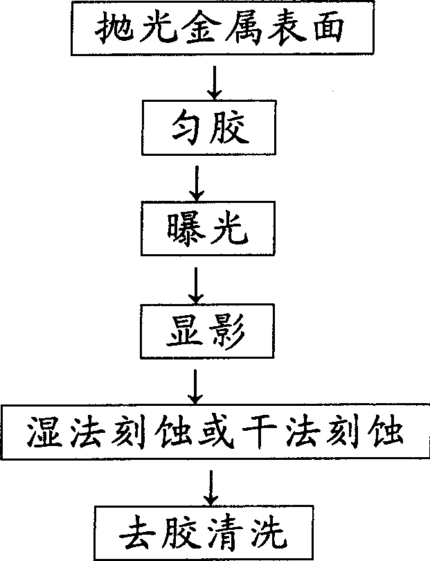
[0014] like figure 1 As shown in the prior art, the method for making a metal grating template is to etch a grating on the metal surface by using a reactive ion etching process of wet etching or dry etching after polishing the metal surface, uniform coating, exposure, and development. Graphics, and then make a metal grating template after degumming.

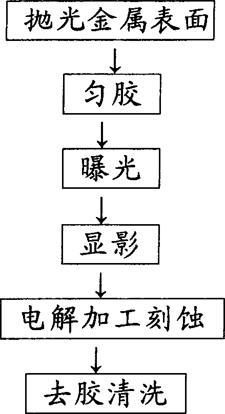
[0015] like figure 2 As shown, the method for making a metal grating stencil by the technology of the present invention is to polish the metal surface, spread the glue, expose, and develop, and then use the electrolytic machining etching process to etch the grating pattern on the metal surface, and then make a metal grating pattern after degumming. Raster template.

[0016] A typical embodiment of the present invention is to make the metal nickel grating stencil of the grating used in the optical disc drive laser head, and its making process is as follows:

[0017] (1) polishing the surface of one side of the grating pattern ...


PUM

PropertyMeasurementUnit
surface roughnessaaaaaaaaaa
depthaaaaaaaaaa

Abstract

The metal grating template making process includes photoetching comprising homogenizing photoresist, exposure, developing and other steps to form photoresist grating pattern; electrolytic etching via setting metal workpiece as positive electrode inside the electrolyte with the grating pattern side set opposite to the negative electrode to etch out the exposed the grating pattern to form grooves while protecting the photoresist masked metal surface; and taking out the metal template after reaching the required etching depth, eliminating photoresist and cleaning to obtain the metal grating template. The metal grating template making process of the present invention is simple, low in cost and fast, and etched pattern is smooth and precise.

Description

technical field [0001] The invention relates to a method for making a metal grating template, in particular to a method for making a metal grating template by using an electrolytic machining and etching process. technical background [0002] Metal grating stencils are used in the replication and mass production of grating elements. At present, the manufacturing process of the metal grating template generally adopts the photolithography process. The photolithography process includes the main processes such as coating, exposure, development, etching, and stripping. Coating is to coat a layer of corrosion-resistant photoresist on the polished metal surface. Exposure is to add a mask with a grating pattern on the photoresist layer, and transfer the grating pattern to the photoresist after illumination. Development is to dissolve and remove the exposed part of the photoresist with a developer, so that the metal surface of the part that needs to be corroded is exposed, while th...

Claims


Application Information

Patent Timeline
Patent Type & Authority Applications(China)
IPC IPC(8): C25F3/14
Inventor 赵泽宇侯德胜杜春雷王长涛
Owner INST OF OPTICS & ELECTRONICS - CHINESE ACAD OF SCI
Why Eureka
Try Eureka