
Method for improving efficiency, saving energy and lowering consumption of wetting intermitten ball mill

A ball mill, intermittent technology, applied in the field of powder processing, can solve the problems of inability to adapt to the optimal rotation speed, low quality of ball milled products, and high power consumption per unit output, narrowing the particle size distribution range of products, and improving the production of ball milled products. quality, the effect of shortening the milling time

Inactive Publication Date: 2006-03-15
唐慧光
View PDF0 Cites 12 Cited by
  • Summary
  • Abstract
  • Description
  • Claims
  • Application Information

AI Technical Summary

Problems solved by technology

The existing wet batch ball mills all work at a fixed speed, which cannot be changed according to the changes in the grinding environment and process conditions during use, such as the difference in the properties of the materials to be ground and the size of the particle size during the grinding process. adjusted for changes in
It can be seen that the ball milling method of the above-mentioned wet batch ball mill has the following disadvantages: (1) it cannot adapt to the requirements of the optimal speed of the wet batch ball mill for materials of different properties; (3) The quality of ball mill products is not high; (4) Long milling time and high power consumption per unit output

Method used


Image

  • Method for improving efficiency, saving energy and lowering consumption of wetting intermitten ball mill
  • Method for improving efficiency, saving energy and lowering consumption of wetting intermitten ball mill
  • Method for improving efficiency, saving energy and lowering consumption of wetting intermitten ball mill

Examples


Embodiment 1

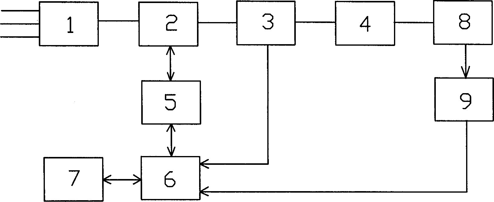
[0013] see figure 1 As shown, a power electronic speed control device is connected to the input end of the wet process intermittent ball mill to automatically adjust the rotation speed of the ball mill drum. 9. The CPU controller 6 and the conversion module 5 form a closed-loop speed regulation system. The frequency converter 2 is powered by an external 380V AC power supply through the air switch 1, and the command issued by the CPU controller 6 is converted by the conversion module 5 and the output control signal is connected to the signal input terminal of the frequency converter 2, and the frequency converter 2 outputs a certain frequency according to the signal , voltage, and electric power parameter signals to control the speed and torque of the ball mill motor 4. The voltage, current and electric power output from the frequency converter 2 to the motor 4 of the ball mill, which reflect load changes, are fed back by the sensor 3 to the CPU controller 6 for analysis and c...

Embodiment 2

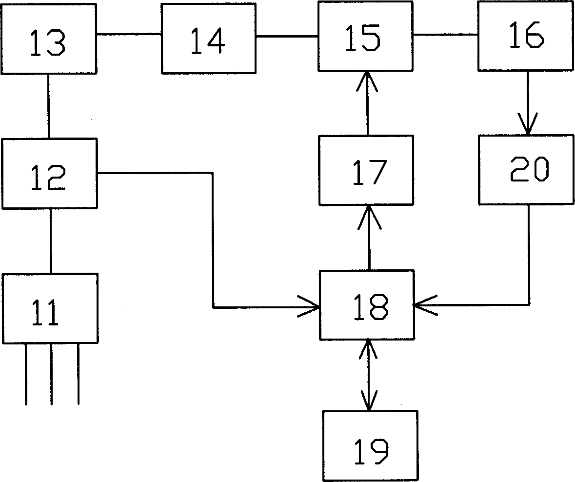
[0022] see figure 2 As shown, a mechanical variable speed regulating device is connected to the input end of the wet intermittent ball mill to automatically adjust the drum speed. The mechanical variable speed regulating device consists of a sensor 12, a ball mill motor 13, a hydraulic coupling 14, a mechanical transmission 15, and 16. Electric and hydraulic manipulators 17, CPU controller 18 and conversion electronic card 20 form a closed-loop speed regulation system.

[0023] The three-phase 380V AC power is input to the ball mill motor 13 through the air switch 11, and the mechanical power output by the motor 13 is output to the mechanical transmission 15 through the hydraulic coupler 14, and the output drives the ball mill 16 cylinder to rotate after the speed change. The gear ratio of the mechanical transmission 15 is controlled by the CPU controller 18 via the electric and hydraulic manipulator 17 . When inputting the voltage, current and electric power of the ball mil...


PUM


Abstract

A method for increasing the efficiency of intermittent wet ball grinder and decreasing energy consumption features that the ball grinder is working at the optimal rotation speed for different materials and different grinding stages. As a result, a speed regulation controller is used to automatically optimize the rotation speed according to the environmental factors of grinding in drum.

Description

technical field [0001] The invention relates to the technical field of powder processing, in particular to a method for improving the efficiency of a wet batch ball mill, saving energy and reducing consumption. Background technique [0002] Wet batch ball mill is a kind of grinding machinery equipment widely used in cement, ceramics, chemical industry, mining, metallurgy and other industries. The existing wet batch ball mills all work at a fixed speed, which cannot be changed according to the changes in the grinding environment and process conditions during use, such as the difference in the properties of the materials to be ground and the size of the particle size during the grinding process. adjusted for changes. It can be seen that the ball milling method of the above-mentioned wet batch ball mill has the following disadvantages: (1) it cannot adapt to the requirements of the optimal speed of the wet batch ball mill for materials of different properties; (3) The quality...

Claims


Application Information

Patent Timeline
IPC IPC(8): B02C25/00B02C17/00
Inventor 唐慧光
Owner 唐慧光
Learn More