Electrochemical earthing body

A grounding body and electrochemical technology, which is applied in the field of electrochemical grounding body, can solve the problems that the resistance reduction effect cannot reach the expected target value, sacrificial anodes should not be used, and the performance-price ratio is unreasonable, etc., and the resistance reduction effect is obvious, Significant resistance reduction effect, high cost performance effect

Inactive Publication Date: 2006-03-22
马春兰 +5
View PDF0 Cites 5 Cited by
  • Summary
  • Abstract
  • Description
  • Claims
  • Application Information

AI Technical Summary

Problems solved by technology

[0036] To sum up, although the sacrificial anode cathodic protection has the function of reducing the grounding resistance, in this way, the non-ferrous metal alloy material is used to reduce the resistance, the cost is too high, and the performance-price ratio is obviously unreasonable
[0037] If the number of anodes is reduced in order to reduce the cost, the resistance reduction effect of this scheme will not reach the expected target value; if the amount of traditional grounding body is increased to reduce the use of sacrificial anodes and reduce the cost, then the sacrificial anode will be in In terms of resistance reduction, it only serves as an embellishment, mainly for cathodic protection; as mentioned above, under geological conditions with high soil resistivity, sacrificial anodes should not be used

Method used


Image

  • Electrochemical earthing body
  • Electrochemical earthing body
  • Electrochemical earthing body

Examples


Embodiment 1

[0104] The components and weight percentages of the drag reducing agent are:

[0105] SiO 2 35.5%; CaSO 4 16.1%; MgSO 4 27.5%; Al 2 o 3 7.9%; Mg(OH) 2 5.7%;Na 2 SO 4 3.1%; MgO 1.65%; CaO 1.35%; Fe 2 o 3 0.75%;K 2 O 0.15%; Na 2 O 0.15%; TiO 2 0.15%;

[0106] After uniformly mixing the powders of each component, the mixture is obtained, which is used as a drag reducing agent for direct construction, and the components interact with each other through underground moisture to achieve the purpose of reducing drag; or, add water according to the mass ratio mixture: water = 1:3 After stirring evenly, it can be used as a drag reducing agent before construction.

Embodiment 2

[0108] The composition and weight percentage of drag reducing agent are: SiO 2 32.0%; CaSO 4 25.2%; MgSO 4 20.0%; Al 2 o 3 7.1%; Mg(OH) 2 8.0%;Na 2 SO 4 4.2%; MgO 1.5%; CaO 1.0%; Fe 2 o 3 0.7%;K 2 O 0.1%; Na 2 O 0.1%; TiO 2 0.1%.

[0109] After uniformly mixing the powders of each component, a mixture is obtained, which is used as a drag reducing agent for direct construction, and the components interact with each other through underground moisture to achieve the purpose of reducing drag; or, add water according to the mass ratio mixture: water = 1: 2.5 After stirring evenly, it can be used as a drag reducing agent before construction.

Embodiment 3

[0111] The composition and weight percentage of drag reducing agent are: SiO 2 39.0%; CaSO 4 7.0%; MgSO 4 35.0%; Al 2 o 3 8.7%; Mg(OH) 2 3.4%; Na 2 SO 4 2.0%; MgO 1.8%; CaO 1.7%; Fe 2 o 3 0.8%;K 2 O 0.2%; Na 2 O 0.2%; TiO 2 0.2%.

[0112] After the powders of each component are uniformly mixed, the mixture is obtained, which is used as a drag reducing agent for direct construction, and the components are interacted with each other through underground moisture to achieve the purpose of reducing drag; or, the mass ratio of the mixture: water = 1: 4.5 After adding water and stirring evenly, it can be used as a drag reducing agent before construction.


PUM

PropertyMeasurementUnit
electrical resistanceaaaaaaaaaa
thicknessaaaaaaaaaa
thicknessaaaaaaaaaa

Abstract

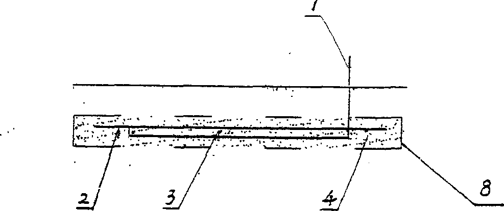
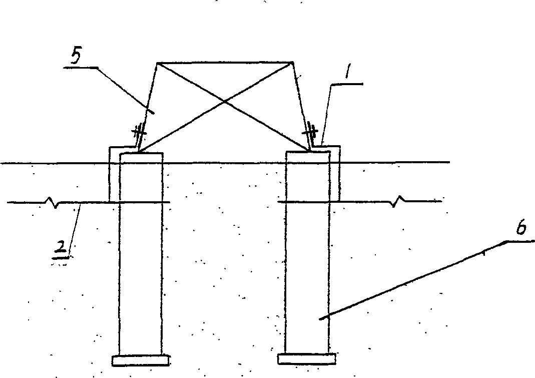
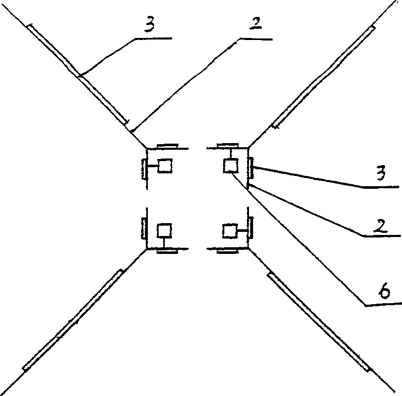
The present invention relates to anticorrosion and resistance lowering technology for earthing body, and is especially one electrochemical earthing body. The electrochemical earthing body has earthing body connected to the lead-down wire, magnesium alloy belt anode connected to and embedded with the earthing body, and resistance lowering agent around the earthing body and the belt anode. The electrochemical earthing body of the present invention integrates traditional earthing mode, resistance lowering agent technology and anode protecting principle, and has low resistance, long effectiveness, no corrosion and other features. The electrochemical earthing body of the present invention has the basic construction mode the same as traditional mode and is suitable for engineering requirement.

Description

technical field [0001] The invention relates to an anti-corrosion and resistance-reducing technology of a grounding body, in particular to an electrochemical grounding body. Background technique [0002] The grounding device is an important part of the voltage protection device and building safety. At present, the grounding bodies of power transmission towers or high-rise buildings are made of metal materials. Because they have been buried underground for many years, most of these materials have not been treated with anti-corrosion treatment, but have been treated with anti-corrosion treatment. The grounding device cannot fundamentally prevent the corrosion process or can only slow down the corrosion to a certain extent, especially the corrosion degree of the buried part is difficult to judge. After several years, it is necessary to dig out the grounding body for inspection. Complete, so the workload is extraordinarily heavy, and it is not convenient. [0003] Overhead line...

Claims


Application Information

Patent Timeline
Patent Type & Authority Applications(China)
IPC IPC(8): C23F13/14
Inventor 常守文马春兰
Owner 马春兰
Why Eureka
Try Eureka