Organic electrolumineescence component and display device containing said organic electroluminescence component

A technology for electroluminescent elements and display devices, applied in electroluminescent light sources, electrical components, electrical light sources, etc., can solve the problem of severe metal doping, unsuitability for large-scale applications, and reduced luminous efficiency and operating life of components. question

Active Publication Date: 2006-03-29
AU OPTRONICS CORP
View PDF0 Cites 15 Cited by
  • Summary
  • Abstract
  • Description
  • Claims
  • Application Information

AI Technical Summary

Problems solved by technology

However, due to the high chemical activity of alkali gold or alkaline earth metals such as cesium (Cs), lithium (Li), and magnesium (Mg), and the doping concentration of the metal is very strict, a slight deviation will lead to a decrease in the luminous efficiency and operation of the device. large variability in lifespan
Therefore, it is not suitable for large-scale application in the thermal evaporation process commonly used in the manufacture of OELD
In addition, the metal ions in the doped layer will diffuse under the trend of current, causing a luminance quenching effect in the organic light-emitting layer, resulting in a decrease in the luminous efficiency and operating life of the device.

Method used


Image

  • Organic electrolumineescence component and display device containing said organic electroluminescence component
  • Organic electrolumineescence component and display device containing said organic electroluminescence component
  • Organic electrolumineescence component and display device containing said organic electroluminescence component

Examples


Embodiment 1

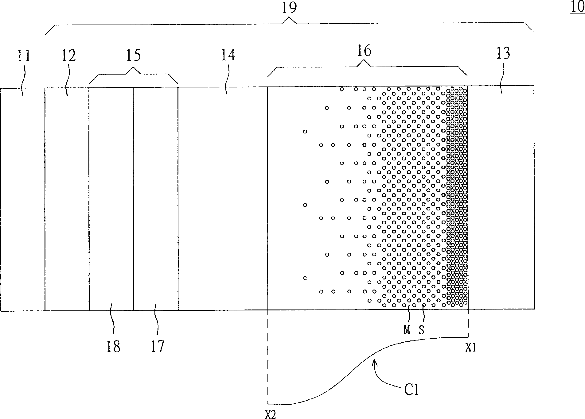
[0033] Please refer to figure 1 , shows a cross-sectional view of a display device including an organic electroluminescent device (OELD) according to Embodiment 1 of the present invention. exist figure 1 Among them, the display device 10 includes a substrate 11 and an organic electroluminescent element 19, the organic electroluminescent element 19 is arranged on the substrate 11, and includes an anode 12, a cathode 13, a light-emitting layer 14, a hole source 15 and An electron source 16 . Wherein, the organic electroluminescent element 19 is illustrated by taking the anode 12 disposed on the substrate 11 as an example, but the technology of this embodiment is not limited thereto. For example, the organic electroluminescent element 19 is disposed on the substrate 11 with the cathode 13 . The light emitting layer 14 is disposed between the anode 12 and the cathode 13 , and the hole source 15 is disposed between the anode 12 and the light emitting layer 14 . The electron sou...

Embodiment 2

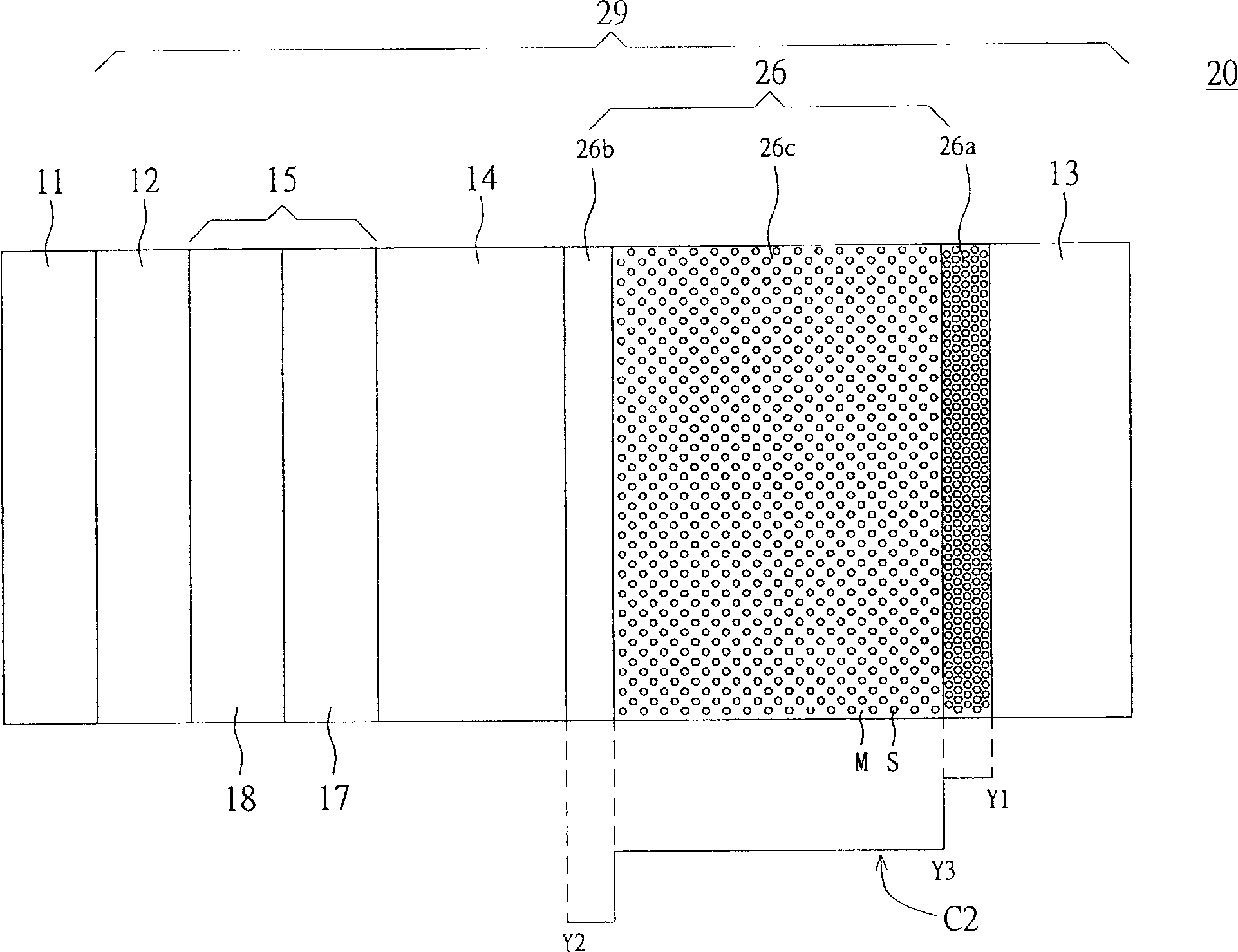
[0045] Please refer to figure 2 , shows a cross-sectional view of a display device including an organic electroluminescent element according to Embodiment 2 of the present invention. The difference between the display device 20 of the present embodiment and the display device 10 of the first embodiment lies in the organic electroluminescent element 29, and the organic electroluminescent element 29 of the present embodiment is different from the organic electroluminescent element 19 of the first embodiment At the electron source 26 . As for the other same constituent elements, the reference numerals will continue to be used and will not be repeated.

[0046] exist figure 2 Among them, the electron source 26 is disposed between the cathode 13 and the light emitting layer 14, and is composed of at least one organic material M and at least one salt S. The salt S has a spatially variable concentration C2 in the electron source 26 such that the concentration Y1 of the salt S at...

Embodiment 3

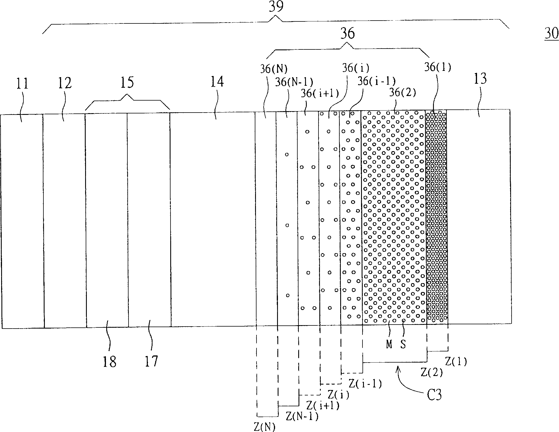
[0053] Please refer to image 3 , shows a cross-sectional view of a display device including an organic electroluminescence element according to Embodiment 3 of the present invention. The difference between the display device 30 of the present embodiment and the display device 20 of the second embodiment lies in the organic electroluminescent element 39, and the organic electroluminescent element 39 of the present embodiment is different from the organic electroluminescent element 29 of the second embodiment At the electron source 36 . As for the other same constituent elements, the reference numerals will continue to be used and will not be repeated.

[0054] exist image 3 Among them, the electron source 36 is disposed between the cathode 13 and the light emitting layer 14, and is composed of at least one organic material M and at least one salt S. The salt S has a spatially variable concentration C3 in the electron source 36 such that the concentration of the salt S is g...


PUM


Abstract

In the invention, an organic electroluminescent element comprises a cathode, an anode, a light-emitting layer, a hole source and an electronic source. The light-emitting layer is disposed between the anode and cathode, and the hole source is disposed between the anode and the light-emitting layer. The electronic source disposed between the cathode and the light-emitting layer is made of at least one kind of organic material and at least one kind of salt. The salt has the concentration capable of changing with the space distribution in the electronic source, so that the concentration of the salt at the electronic near the cathode is higher than that at the electronic source near the light-emitting layer.

Description

technical field [0001] The present invention relates to an organic electroluminescent device (organic electroluminescent device, OELD) and a display device comprising the organic electroluminescent device, in particular to an organic electroluminescent device in which the concentration of salts in the electron source varies with the spatial distribution. An excitation light element and a display device including an organic electroluminescence element. Background technique [0002] Regarding the development of OELD, since the material of the cathode must be a metal with a low work function, the reactivity itself needs to be very strong, so the early industry used magnesium to add a small amount of silver (probably with a ratio of ten to one) as a very good solution. Alloys for cathode electrodes. However, highly reactive metals are extremely unsuitable for the OELD process, so the industry then uses passive metals, such as aluminum, as electron injection electrodes. However...

Claims


Application Information

Patent Timeline
Patent Type & Authority Applications(China)
IPC IPC(8): H05B33/14G09F9/30
Inventor 刘醇炘李重君
Owner AU OPTRONICS CORP
Why Eureka
Try Eureka