Supersonic wave waveguide device

A waveguide device, ultrasonic technology, applied in the direction of ultrasonic therapy, treatment, massage auxiliary products, etc., can solve the problems of piezoelectric chip burnout, piezoelectric chip driving voltage can not be increased infinitely, piezoelectric chip is inconvenient to move, etc.

Active Publication Date: 2006-04-05
CHONGQING HAIFU MEDICAL TECH CO LTD
View PDF0 Cites 2 Cited by
  • Summary
  • Abstract
  • Description
  • Claims
  • Application Information

AI Technical Summary

Problems solved by technology

However, the driving voltage of the piezoelectric chip cannot be increased indefinitely, otherwise the piezoelectric chip will be burned, so the second method is often used clinically, but it is very inconvenient to move the large piezoelectric chip when performing treatment

Method used


Image

  • Supersonic wave waveguide device
  • Supersonic wave waveguide device
  • Supersonic wave waveguide device

Examples


Embodiment Construction

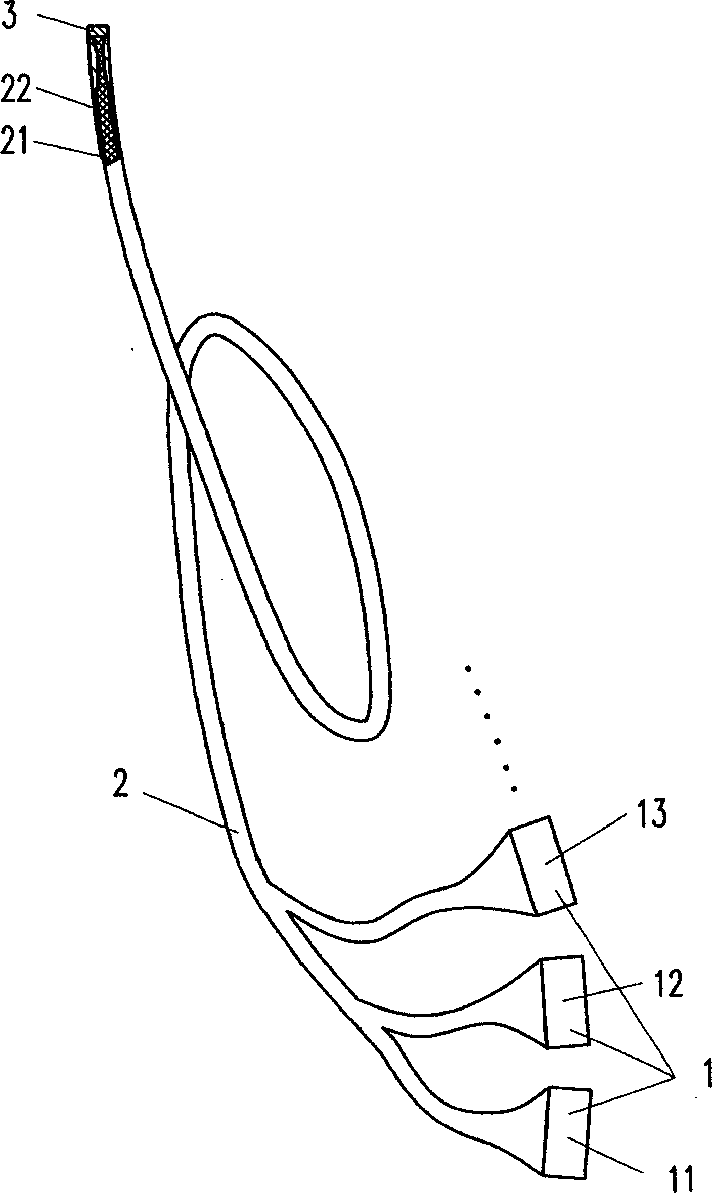
[0023] Such as figure 1 As shown, the ultrasonic treatment device with waveguide of the present invention includes three piezoelectric wafers 1 , a waveguide 2 with a branch at one end, and a coupling medium 3 . One end of each piezoelectric wafer 1 (11, 12, 13) is connected to a branch pipe of the waveguide 2, and the other ends of each branch waveguide converge to form a main waveguide. The waveguide 2 can transmit the ultrasonic energy emitted by the piezoelectric chip 1 to the treatment site. The waveguide 2 can be rigid or flexible as required.

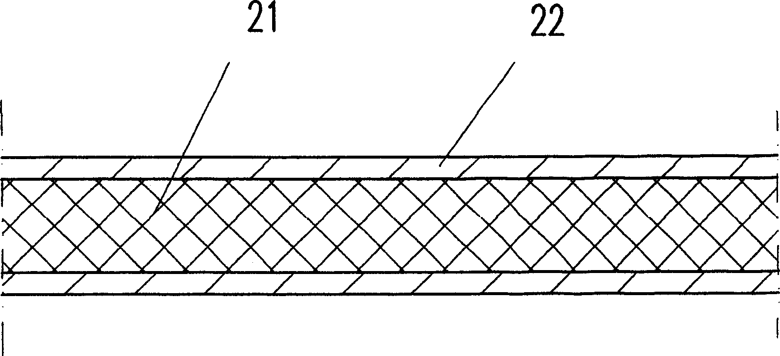
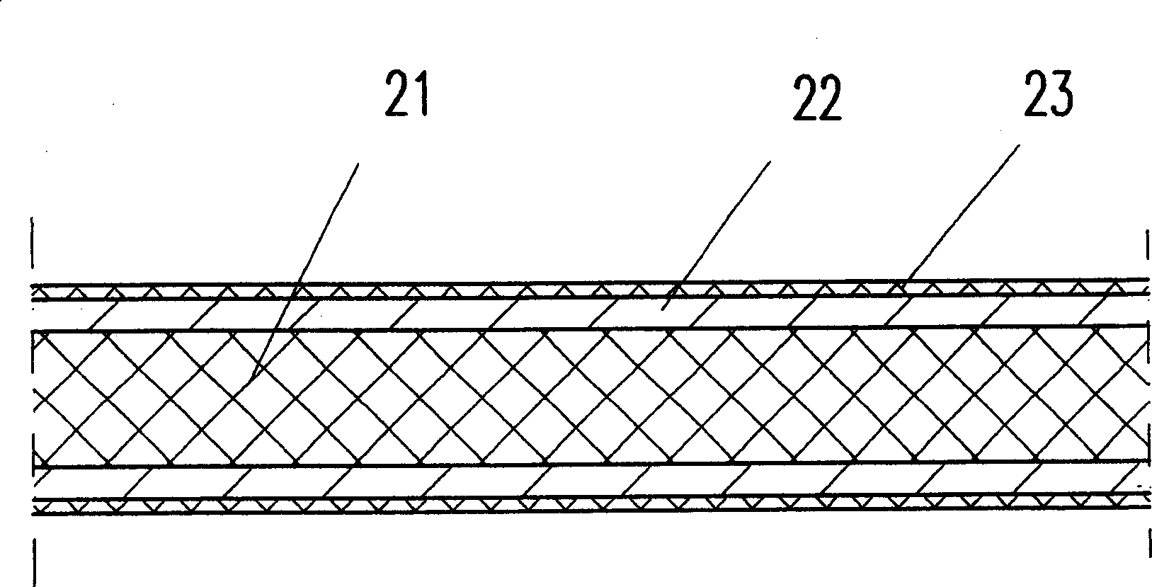
[0024] figure 2 A schematic diagram of the waveguide structure. The waveguide 2 includes a core layer 21 and an outer layer 22 . The sound velocity of the core layer 21 is much smaller than that of the outer layer 22 . When the ultrasonic wave is injected into the core layer 21, the ultrasonic wave will propagate forward along the core layer 21. The interface with the core layer 21 produces total reflection, so that the ul...


PUM


Abstract

The invention provides a waveguide device for the supersonic wave, comprising: morph, the waveguide which can transmit the supersonic wave released by the morph to the position far away from the morph, one end of the waveguide is connected with the morph fixedly, the other end of the waveguide is the free end. The device in this invention can move the supersonic wave focal point conveniently without the increase of the morph driving voltage, which provides great convenience for the clinical therapy.

Description

Field of invention: [0001] The invention belongs to medical devices, and in particular relates to a medical device for treating with ultrasonic waves. Background technique: [0002] High-intensity focused ultrasound (HIFU) has been clinically approved as a new method for the treatment of tumors and other diseases, and is used for early localized prostate cancer, middle and advanced liver cancer, breast cancer, osteosarcoma, and soft tissue sarcoma , kidney cancer and other malignant tumors and benign diseases such as glaucoma, benign prostatic hyperplasia and leukoplakia, and achieved good therapeutic effects. [0003] High-intensity focused ultrasound is to focus the ultrasound emitted by the piezoelectric chip to a point, and use the thermal effect, mechanical effect, and cavitation effect of the ultrasound at the focal point to treat diseased tissues. In order to make the energy at the focal point large enough, two methods can be adopted, one is to increase the driving v...

Claims


Application Information

Patent Timeline
Patent Type & Authority Applications(China)
IPC IPC(8): A61N7/00A61N7/02A61H23/00
Inventor 赵纯亮王智彪王芷龙
Owner CHONGQING HAIFU MEDICAL TECH CO LTD
Why Eureka
Try Eureka