

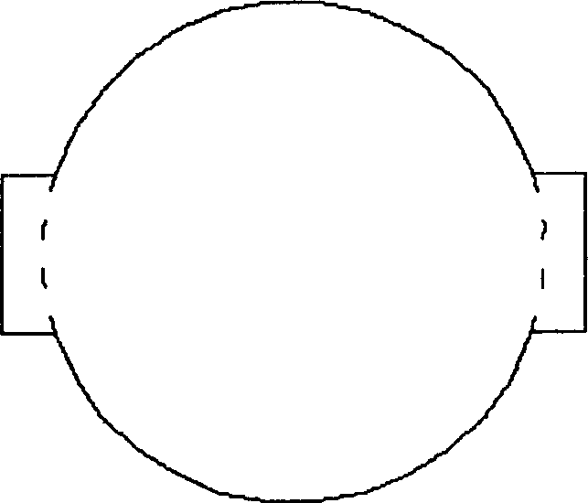
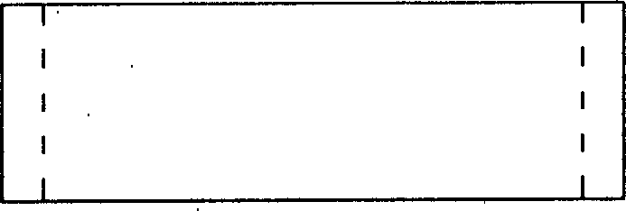
Float valve fixing column plate
A technology of float valve tray and valve plate, which is applied in the direction of fractionation, etc., can solve the problems of weakening, reducing plate efficiency, weakening the mass transfer function of the tray, etc., and achieve the effects of reducing resistance, increasing flux and reducing resistance
- Summary
- Abstract
- Description
- Claims
- Application Information
AI Technical Summary
Problems solved by technology
Method used
Image


Examples
Embodiment 1
[0019] Propylene oxide (PO)-water rectification system adopts the fixed valve tray of the present invention to transform the original F1 type valve tray, the tower diameter is Φ1200mm, the number of trays is 50, the plate spacing is 450mm, and the material is stainless steel. Use fixed valve tray of the present invention instead, as Figure 5 , Figure 6 As shown, the length of the long side of the valve plate a = 50mm; the width of the valve plate b = 25mm; the width of the valve leg c = 8mm; the total length of the valve plate d = 70mm; the height of the solid valve h = 4mm; the length of the valve hole It is 1=75mm. Such as Figure 7 As shown, the fork row method is adopted, the valve center distance s=70mm, the distance between rows t=60mm, and the processing capacity is F=18000t / a=2500kg / h (calculated on the basis of 300 days a year). The operation results show that the processing capacity of this tray is 15% higher than that of the F1 float valve, the purity of PO aft...
Embodiment 2
[0021] The ethanol-water rectification system was originally an ordinary sieve tray. The equipment has been abnormal since it was put into operation. The main performance is that the production load is low, which can only reach 90% of the original design load, and the product is unqualified if the working conditions and load fluctuate slightly. After many observations, adjustments, and repeated calculations It is considered that the efficiency of the tray is reduced because the gas perforation velocity is too large. In order to improve the condition of this set of equipment, the fixed valve tray of the present invention is adopted. The original rectification tower is Φ1600mm, with 55 trays, and the opening ratio is 12%. All trays are changed into fixed valve trays of the present invention. Such as Figure 5 , Figure 6 As shown, the length of the long side of the guide valve plate is a=40mm; the width of the valve plate is b=20mm; the width of the valve leg is c=6mm; the l...
PUM
| Property | Measurement | Unit |
|---|---|---|
| Length | aaaaa | aaaaa |
| Width | aaaaa | aaaaa |
| Width | aaaaa | aaaaa |
Abstract
Description
Claims
Application Information