
Electrically controlled multi-point sequential injection system and control method for natural gas engine

A sequential injection, engine technology, applied in engine control, fuel injection control, electrical control and other directions, can solve the increase in heat generation of MOSFET tubes and solenoid valve coils, reduce the stability and reliability of components and systems, and increase the difficulty of heat dissipation and other problems, to achieve the effect of reducing heat dissipation, reducing volume and easy installation

Inactive Publication Date: 2006-04-26
BEIJING JIAOTONG UNIV
View PDF1 Cites 11 Cited by
  • Summary
  • Abstract
  • Description
  • Claims
  • Application Information

AI Technical Summary

Problems solved by technology

In this way, the circuit will consume more energy when it works, and the heat generated by the MOSFET tube and the solenoid valve coil will also increase significantly, which will increase the difficulty of heat dissipation and may reduce the stability and reliability of components and system work.

Method used

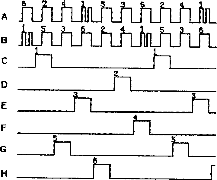
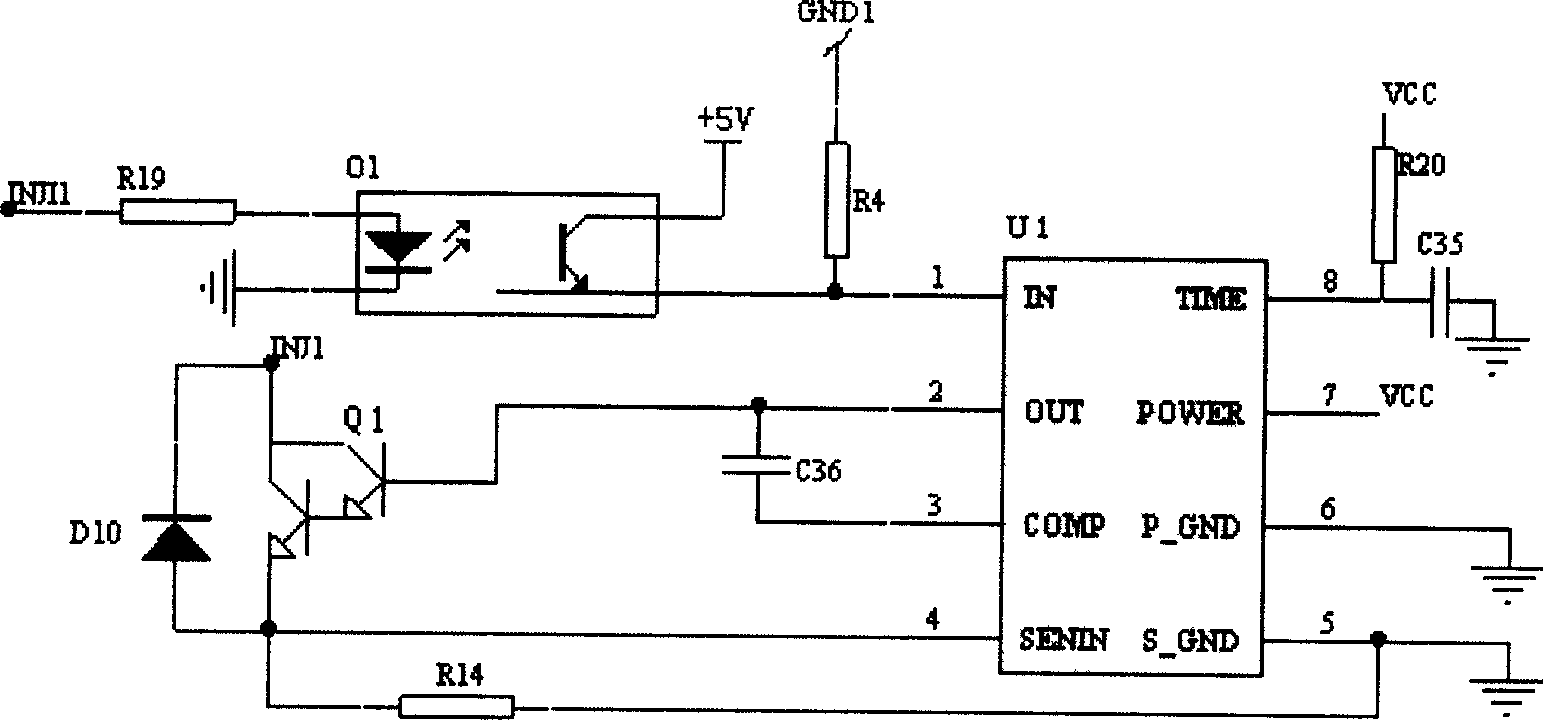

Image

  • Electrically controlled multi-point sequential injection system and control method for natural gas engine
  • Electrically controlled multi-point sequential injection system and control method for natural gas engine
  • Electrically controlled multi-point sequential injection system and control method for natural gas engine

Examples


Embodiment Construction

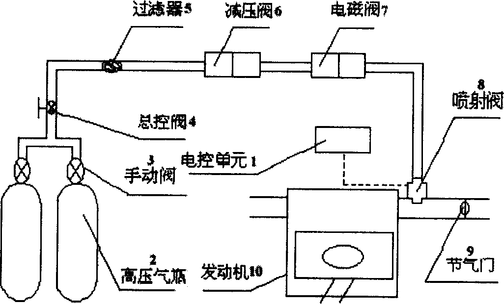
[0019] Below in conjunction with accompanying drawing, the implementation of the present invention is further described as follows: the present invention is achieved in this way. The system is mainly composed of electronic control unit 1 (see figure 1 ), high-pressure gas cylinder 2, manual valve 3, master control valve 4, filter 5, pressure reducing valve 6, solenoid valve 7, fuel injection valve 8, throttle valve 9, engine 10 and corresponding pipelines. CNG is stored in the high-pressure gas cylinder 2 with a pressure of 20MPa. When the engine 10 is working, the manual valve 3 of the gas cylinder is opened, and the CNG flows through the master control valve 4, and the impurity in the gas fuel is removed through the filter 5. CNG flows through the pressure reducing valve 6 to reduce to the required low pressure, enters the gas rail, and finally passes through the air injection solenoid valve 7 on the gas rail under the control of the electronic control unit (model: SP-21, Gu...


PUM


Abstract

The invention relates to an electric control injection system of natural gas engine for controlling the natural gas injection quantity, which is characterized by the following: adding the natural gas supply system; adapting gas-valve injecting supply pattern; setting the valve in the root of inlet pipe. The invention improves the gas-valve activation circuit to guarantee each cylinder with quantitative gas supply, which controls the zero-burn ratio according to the rotary speed and load.

Description

Technical field [0001] The invention relates to an electronically controlled multi-point sequential injection system and a control method for a natural gas engine. Background technique [0002] At present, domestic CNG engines for vehicles are all converted from gasoline engines or diesel engines, and there are relatively few engines specially designed and manufactured according to the combustion characteristics of CNG. For CNG engines, the fuel supply system can be divided into intake manifold mixer mode, intake manifold single-point injection mode, intake manifold multi-point injection mode and in-cylinder direct injection mode according to the control mode. The mixer-type CNG supply system does not have high control precision for the CNG supply, cannot accurately control the air-fuel ratio, and has limited improvement in engine emission performance. Moreover, the engine's power and economy are affected due to the decrease in engine charging efficiency. The single-point i...

Claims


Application Information

Patent Timeline
Patent Type & Authority Applications(China)
IPC IPC(8): F02D41/26
Inventor 郭林福张欣刘建华芦畅
Owner BEIJING JIAOTONG UNIV
Learn More