Nitrogen dioxide gas concentration monitoring system and monitoring method thereof

A technology of gas concentration and nitrogen dioxide, applied in the direction of color/spectral characteristic measurement, etc., can solve the problems of high maintenance cost and high price

Inactive Publication Date: 2006-05-03
HARBIN INST OF TECH
View PDF0 Cites 3 Cited by
  • Summary
  • Abstract
  • Description
  • Claims
  • Application Information

AI Technical Summary

Problems solved by technology

[0003] The purpose of the present invention is to provide a nitrogen dioxide gas concentration monitoring ...

Method used


Image

  • Nitrogen dioxide gas concentration monitoring system and monitoring method thereof
  • Nitrogen dioxide gas concentration monitoring system and monitoring method thereof

Examples


specific Embodiment approach 1

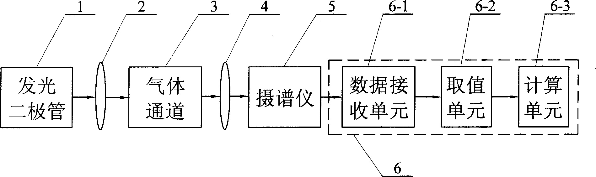
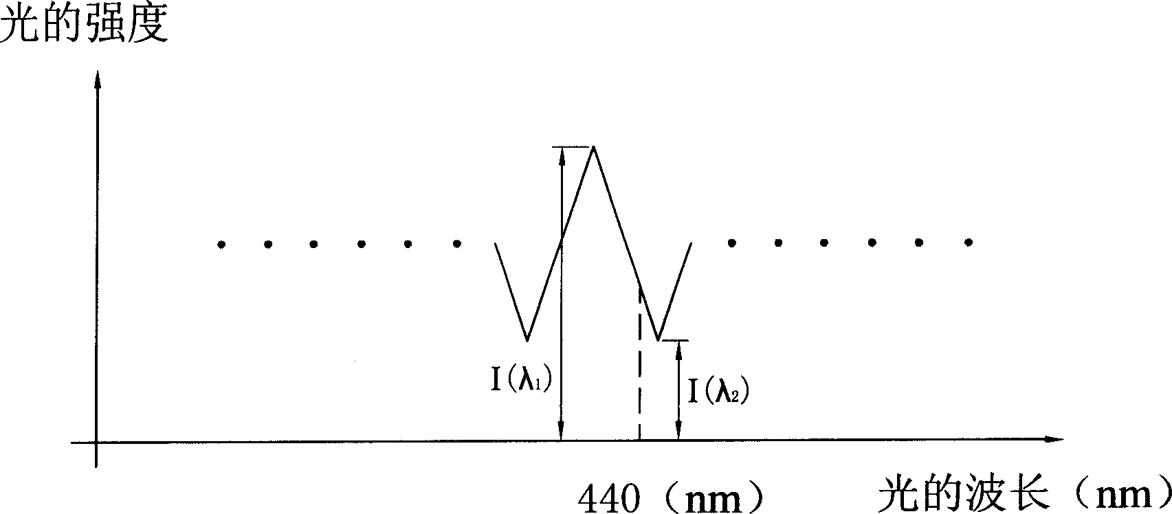
[0006] Specific implementation mode one: combine figure 1 and figure 2 Describe this embodiment in detail, this embodiment is made up of LED 1, No. 1 convex lens 2, gas channel 3, No. 2 convex lens 4, spectrograph 5, computer 6; No. 1 convex lens 2, gas channel 3 and No. 2 convex lens 4 It is located between the light-emitting diode 1 and the spectrograph 5, and the light emitted by the light-emitting diode 1 is input to the light detection input end of the spectrograph 5 through the first convex lens 2, the gas channel 3 and the second convex lens 4 in sequence, and the spectrograph 5 The data output terminal of computer 6 is connected with the data input terminal of computer 6; Computer 6 obtains the data receiving unit 6-1 of measured gas spectrum from spectrograph 5, can get the peak value I( lambda 1 ) and valley I(λ 2 ) value unit 6-2 and the peak value I(λ 1 ) and valley I(λ 2 ) into N=-Ln[I(λ 1 )÷I(λ 2 )]÷{[σ(λ 1 )-σ(λ 2 )]×L} formula to calculate NO 2 The c...

specific Embodiment approach 2

[0007] Specific implementation mode two: combination figure 1 and figure 2 Describe this embodiment in detail, and this embodiment is made up of following steps: One, spectral extraction step: make nitrogen dioxide gas flow into gas channel 3, make the light that light-emitting diode 1 sends pass successively through No. 1 convex lens 2, gas channel 3 and two No. convex lens 4 is input to the optical detection input end of spectrograph 5, and spectrograph 5 extracts spectrum; Two, NO 2 Gas concentration calculation steps: the spectrum extracted by the spectrograph 5 is received by the data receiving unit 6-1 in the computer 6; The peak I(λ 1 ) and valley I(λ 2 ), the value of the wavelength A is any numerical value in the range of 420 to 460; then the peak value I of the wave (λ 1 ) and valley I(λ 2 ) into N=-Ln[I(λ 1 )÷I(λ 2 )]÷{[σ(λ 1 )-σ(λ 2 )]×L} formula to calculate NO 2 Gas concentration, σ(λ in the formula 1 ) for NO 2 at wavelength λ 1 The absorption cros...


PUM


Abstract

The invention relates to a system and method for monitoring nitrogen oxide density. The system is formed by an illuminate diode 1, a number one convex lens 2, a air channel 3, a number two convex lens 4, a spectrograph 5 and a computer 6, wherein 1 sends the light which is through 2,3,4 and into the light testing input end of 5; the data receiving unit of the tested gas of 6 from 5 can get the peak value I (ª™1)which is adjacent to the wavelength Anm and the alcove value I (ª™2) unit of the spectrum; it also can substitute the ª™1 and ª™2 into the formula Nú¢-Ln[I(ª™1)í‰I(ª™2)]í‰{[ªÊ(ª™1)-ªÊ(ª

Description

technical field [0001] The invention relates to a nitrogen dioxide gas concentration monitoring system, and also relates to a nitrogen dioxide gas concentration monitoring method. Background technique [0002] With the development of the economy, nitrogen dioxide emitted into the air continues to increase. If pollutants such as nitrogen dioxide emitted by coal-fired power plant boilers are not controlled, serious urban air pollution and environmental pollution will result. Therefore, online monitoring of pollutant emissions from coal-fired power plant boilers is imperative. At present, the technologies for on-line gas monitoring mainly include differential absorption spectroscopy (DOAS) technology and laser radar (LIDAR) technology. Among them, the DOAS technology generally uses an optical parametric oscillator as the emission source, but the optical parametric oscillator is expensive, and this technology has high requirements on spectroscopic instruments and detection dev...

Claims


Application Information

Patent Timeline
IPC IPC(8): G01N21/31
Inventor 徐峰张治国
Owner HARBIN INST OF TECH
Why Eureka
Try Eureka