Transmitter circuit, receiver circuit, clock data recovery phase locked loop circuit, data transfer method and data transfer system

A transmission system and transmission circuit technology, applied in the field of coding circuits, can solve the problems of insufficient reduction of clock recovery errors, missynchronization, and quality degradation of transmission paths.

Active Publication Date: 2006-05-10
THINE ELECTRONICS
View PDF2 Cites 17 Cited by
  • Summary
  • Abstract
  • Description
  • Claims
  • Application Information

AI Technical Summary

Problems solved by technology

[0013] However, in the method of Patent Document 1, there are problems such as the following: since a common mode driver is required on the receiving unit side and a common mode voltage detection circuit is required on the transmitting side, it becomes a problem due to parasitic capacitance, noise, etc. of these additional circuits. Main Causes of Transmission Path Quality Deterioration
[0022] The inventors of the present invention think that: in the above-mentioned prior known serial transmission technology, when there are multiple rising edges in one symbol in the serial data, the rising edges are sometimes mistaken for symbol division and missynchronization occurs, which is The cause of the failure to sufficiently reduce the occurrence of errors in clock recovery when converting serial data into parallel data

Method used


Image

  • Transmitter circuit, receiver circuit, clock data recovery phase locked loop circuit, data transfer method and data transfer system
  • Transmitter circuit, receiver circuit, clock data recovery phase locked loop circuit, data transfer method and data transfer system
  • Transmitter circuit, receiver circuit, clock data recovery phase locked loop circuit, data transfer method and data transfer system

Examples


Embodiment 1

[0220] In this embodiment, another example of the first encoding circuit 2504a of the digital data transmission system of the present invention described in the above embodiments will be described. In addition, since other configurations are the same as those described in the above-mentioned embodiment, description thereof will be omitted here.

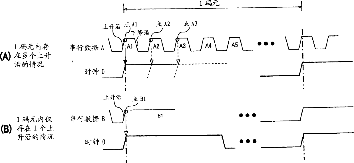
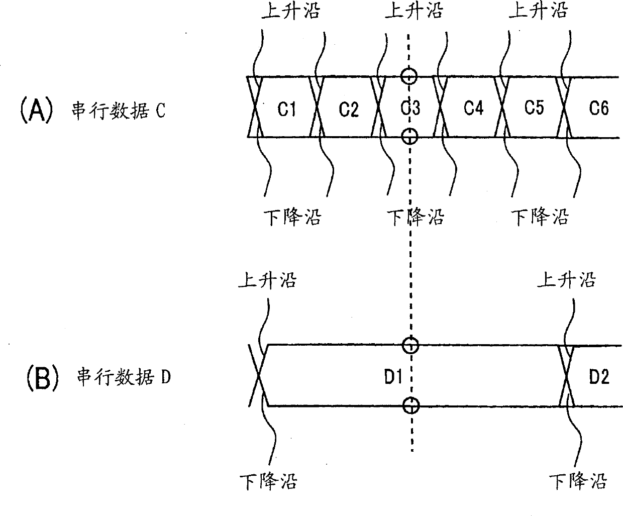
[0221] Refer to FIG. 30 . FIG. 30 is a diagram showing an example of data errors that occur when digital data is serially transmitted. In the data transmission system of the present invention, since serial digital data is transmitted at high speed using a pair of wires or cables, in the case of long-distance transmission by extending the length of wires or cables, or in the case of wiring or cables When the characteristics are poor, the waveform of digital data becomes dull, and bit errors due to ISI (Intersymbol Interference: Intersymbol Interference) tend to occur. This data error, as shown in FIG. 30 , appears conspicuously when ...

Embodiment 2

[0230] Example 2 is another example of the encoding method of the data transmission system described in the above-mentioned embodiments. In addition, since other configurations are the same as those described in the above-mentioned embodiment, description thereof will be omitted here.

[0231] The characteristic feature of this embodiment is that the transmitting unit 2501 has a DC balance circuit and performs encoding so as to achieve DC balance of the serial data. This DC balance circuit counts the accumulation of "high" (=1) and the accumulation of "low" (=0) of encoded data, and feeds back a signal corresponding to the counted number to the evaluation function. This feedback causes the evaluation function to select an encoding mode so that the accumulation of "high" (=1) and the accumulation of "low" (=0) of encoded data converge to the same number. The function of this DC balance circuit is called DC balance processing.

[0232] Here, the encoding method in the data tra...

Embodiment 3

[0246] Embodiment 3 is another example of the clock restoration phase synchronization circuit (clock extraction circuit) in the data transmission system of the above-mentioned embodiment.

[0247] Refer to Figure 36. FIG. 36 is a hardware block diagram showing the circuit configuration of a clock restoration phase synchronization circuit (clock extraction circuit) 2600 as a receiving circuit of the present invention. The clock extraction circuit 2600 of this embodiment is a clock extraction circuit that further includes the trimming frequency comparison circuit 80 in the clock extraction circuit 2523 described in the above embodiment. In addition, description of the same constituent elements as those described in the above-mentioned embodiment is omitted here.

[0248] The clock recovery phase synchronization circuit 2600 of this embodiment has a fine-tuning frequency comparison circuit 80, and after frequency adjustment (coarse frequency adjustment) of the voltage-controlled...


PUM


Abstract

Realizes stable digital data transmission with high reliability and does not require reference clocks and interactive operations. According to the present invention, there is provided a transmission method, which is a digital data transmission method in which the first information and the second information are alternately and periodically transmitted in the first period and the second period, wherein the first The amount of information per unit time of the first information in the period is larger than the information amount per unit time of the second information in the second period; the second information in the first period is pulse width modulated After the serial data to transmit.

Description

technical field [0001] The present invention relates to a transmission circuit and a reception circuit for serializing and transmitting parallel digital data, an encoding circuit used in the transmission circuit, a data transmission method and a data transmission system using them. [0002] Furthermore, the present invention relates to a receiving circuit of a serial data transmission system that serializes parallel digital data to receive, and relates in detail to a clock recovery phase synchronization circuit (also called a CDRPLL circuit: clock circuit) in a receiving unit of the serial data transmission system. data recovery phase-locked loop circuit or clock extraction circuit). Background technique [0003] In recent years, in digital data transmission between devices, higher-speed serial transmission is increasingly desired. The serial transmission of digital data has the following characteristics: Compared with the parallel transmission of digital data, the wiring f...

Claims


Application Information

Patent Timeline
Patent Type & Authority Applications(China)
IPC IPC(8): H04L25/49H03M9/00H04L7/033H04N11/04
Inventor 小沢诚一冈村淳一石曾根洋平三浦贤
Owner THINE ELECTRONICS
Why Eureka
Try Eureka