Magnetic controlled valveless pulsate blood pump
A magnetic control and blood pump technology, which is applied in the field of blood pumps, can solve the problems of large volume and small force-energy density of blood pumps, and achieve the effects of small volume, improved load capacity, and reduced excitation power
- Summary
- Abstract
- Description
- Claims
- Application Information
AI Technical Summary
Problems solved by technology
Method used
Image

Examples
Embodiment 1
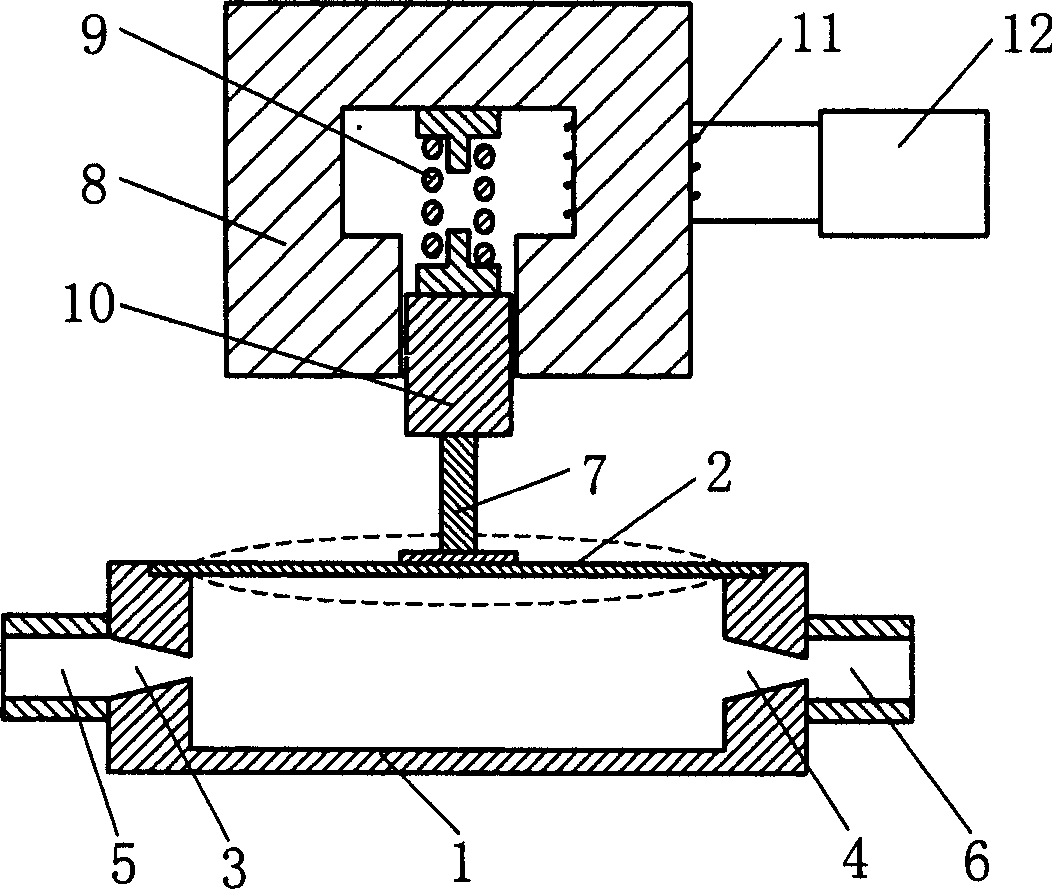
[0020] Embodiment 1: as figure 1 As shown, a valveless blood pump with an electromagnetic drive. The electromagnetic driver includes a magnetically conductive core 8, a magnetically conductive moving iron 10, a return spring 9 and a control winding 11. The connection relationship is: the cross section of the magnetically conductive core 8 is a rectangular frame with an opening, and the magnetically conductive moving iron 10 is placed on the conductive magnet. In the opening of the core 8, the lower end of the magnetically conductive moving iron 10 is connected with the connecting rod 7 of the valveless pump. A return spring 9 is installed between the upper end of the magnetically conductive moving iron 10 and the inner wall of the magnetically conductive core 8. The return spring 9 has an upper and lower Limiting top cover and bottom cover, the top cover is fixed on the inner wall of the magnetically conductive core 8, the bottom cover is fixed on the upper surface of the magn...
Embodiment 2
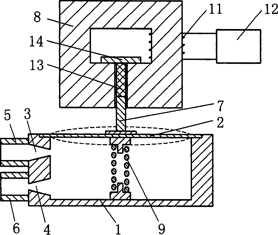
[0022] Embodiment 2: as figure 2 As shown, a valveless blood pump using a magnetically controlled shape memory alloy driver. The magnetically controlled shape memory alloy driver uses a nickel-manganese-gallium alloy magnetically controlled element 13 to replace the magnetically conductive moving iron 10 in Embodiment 1, and the return spring 9 is placed in the pump body 1 of the valveless pump. The specific structure is: The top cover of the back-moving spring 9 is fixed on the elastic plate 2 on the valveless pump, the bottom cover is fixed on the inner surface of the lower wall of the valveless pump pump body 1, and the baffle plate 14 is fixed above the opening inside the guide magnetic core 8. Between the plate 14 and the connecting rod 7 of the valveless pump is the magnetic control element 13, which is in surface contact with the connecting rod 7 and the baffle plate 14, and the magnetic control element 13, the connecting rod 7 and the permeable magnetic core 8 There ...
Embodiment 3
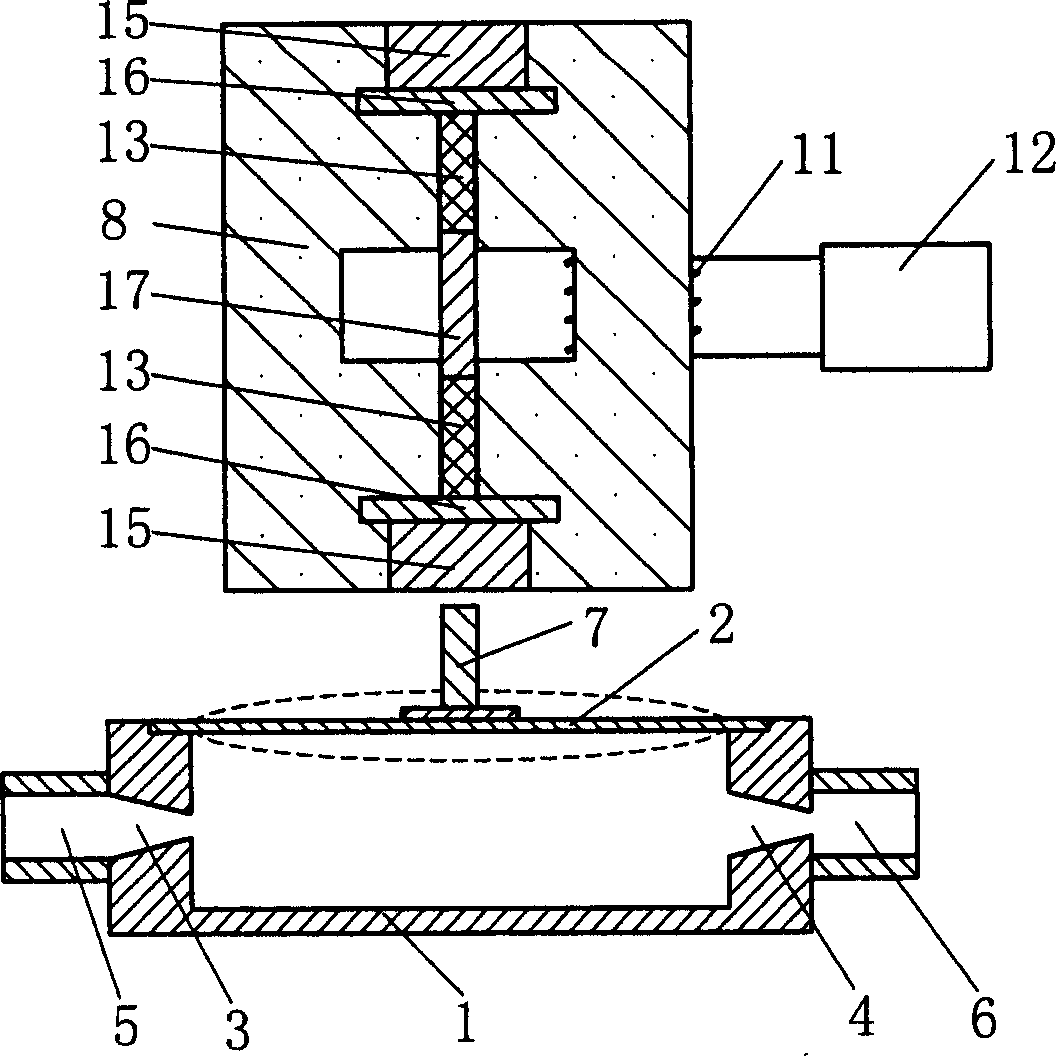
[0024] Embodiment 3: as image 3 , Figure 4 , Figure 5 As shown, a valveless blood pump using a permanent magnet bias differential control magnetic driver. It is an improved structure of Example 1 and Example 2, canceling the return spring, and adopting a permanent magnet bias magnetic circuit and a differential control method. Its structure includes non-magnetic coupling 17, control winding 11, coupling 19, connecting plate 18, two magnetic cores 8 with the same structure, permanent magnets 15 with the same size, performance and horizontal magnetization direction, non-magnetic A magnetic isolation plate 16; a nickel-manganese-gallium alloy magnetic control element 13 with the same size and performance, the connection relationship is: the two ends of the connector 17 are respectively a magnetic control element 13, a magnetic isolation plate 16, and a permanent magnet 15. The side is the magnet core 8, and the center of the magnet core 8 has a groove. In the middle of the...
PUM
 Abstract
Description
Claims
Application Information
 - R&D
- Intellectual Property
- Life Sciences
- Materials
- Tech Scout
- Unparalleled Data Quality
- Higher Quality Content
- 60% Fewer Hallucinations
Browse by: Latest US Patents, China's latest patents, Technical Efficacy Thesaurus, Application Domain, Technology Topic, Popular Technical Reports.
© 2025 PatSnap. All rights reserved.Legal|Privacy policy|Modern Slavery Act Transparency Statement|Sitemap|About US| Contact US: help@patsnap.com