Method for processing integrated reducing multi-way pipe fitting
A processing method and an integrated technology, applied in the direction of tubular objects, other household appliances, household appliances, etc., can solve the problems of poor product performance, high mold cost, and large equipment investment, so as to achieve good product performance, simple equipment and molds, The effect of low investment cost
- Summary
- Abstract
- Description
- Claims
- Application Information
AI Technical Summary
Problems solved by technology
Method used
Image

Examples
Embodiment 1
[0027] The main diameter of the integrated multi-way pipe with different diameters processed in this embodiment ranges from 315 mm to 800 m, and the branch diameter ranges from 63 mm to 250 mm.
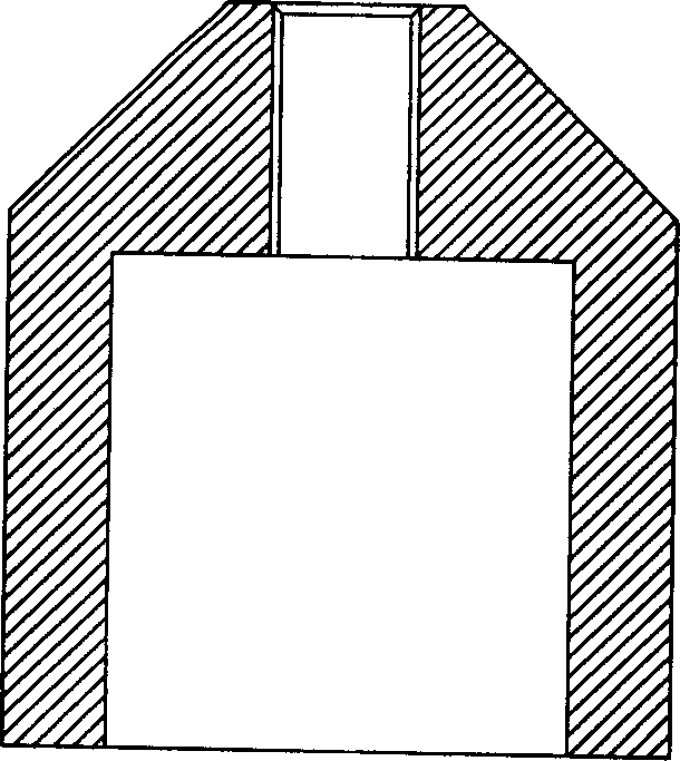
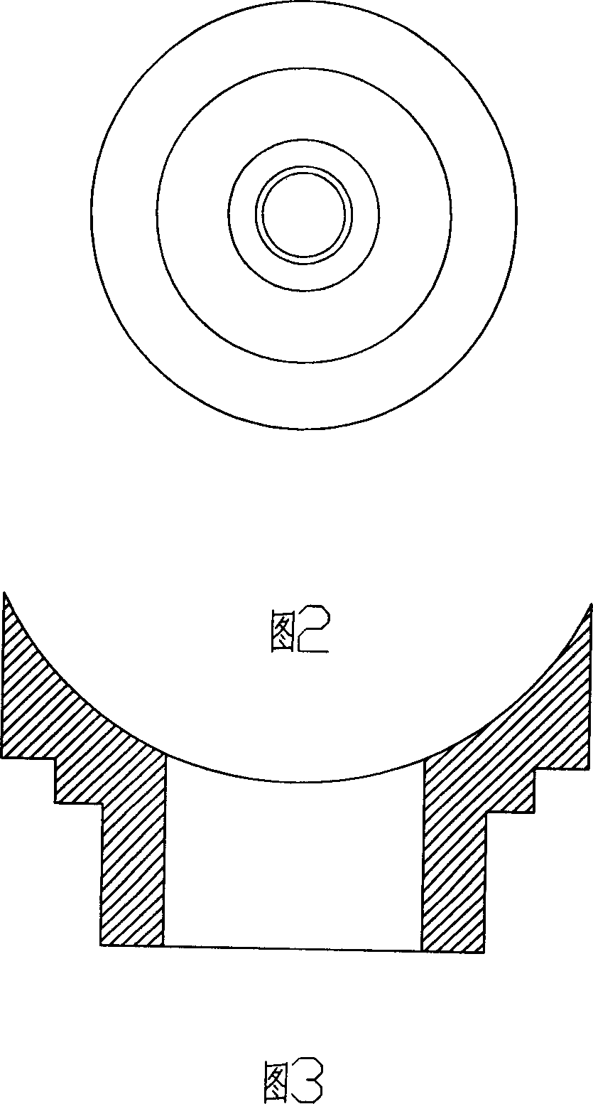
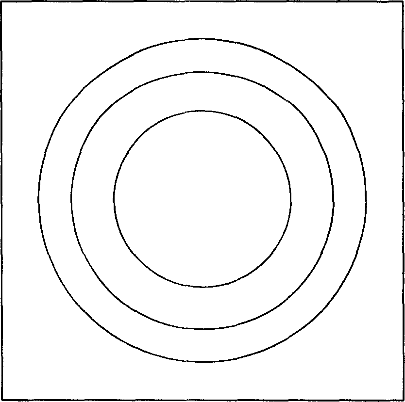
[0028] The processing method steps are as follows (see Figure 1-Figure 6 ):
[0029] 1. Prepare pipe sections of appropriate length
[0030] This length must meet the shortest length of the butt joint.
[0031] 2. Drill holes of a certain size on the pipe section
[0032] The purpose of punching holes is to facilitate the operation of step 4. The number of holes is determined according to the product requirements. The minimum size of the hole should be greater than the diameter of the cylinder rod, and the maximum size is determined by the outer diameter of the branch and the length of the branch. It must be ensured that the branch meets the welding conditions.
[0033] 3. Heating the area to be processed (the outer surface around the pipe hole)
[0034] Start the heating switch...
Embodiment 2
[0045] In this embodiment, the φ315 / 110 one-piece reducing four-way is processed.
[0046] First cut out a PE100 pipe section of φ315, SDR17, and 700mm in length, then symmetrically drill two φ40 holes in the center of the pipe section, set the temperature of the heating device at 260°C, place the pipe section on the heating table, and place one of them after positioning Heating around the hole is controlled by a timer for 30 minutes and then the branch is processed. At this time, a φ315 / 110 sizing sleeve and a φ110 mold core are required. core. In the same way, complete the processing of the other branch. Finally, lengthen and weld the two branches, respectively butt-weld a φ110, SDR11, 320mm long PE100 pipe section (the other end of the pipe section is SDR17).
Embodiment 3
[0048] In this embodiment, the φ400 / 90 flange type one-piece reducing tee is processed.
[0049] Cut out a φ400, SDR17, 700mm long PE100 pipe section, then drill a φ40 hole in the center of the pipe section, set the temperature of the heating device at 190°C, place the pipe section on the heating table, heat the hole around the hole after passing the positioning, and pass the timing After controlled heating for 40 minutes, the branch is processed. At this time, a φ400 / 90 sizing sleeve and a φ90 mold core are required. After molding, the temperature is kept at 80°C. After half an hour, the sizing sleeve and the mold core are removed. Finally, the branch welding is carried out. First, it is butt welded with the φ90, SDR11, and 260mm long PE100 pipe section, and finally it is welded with the φ90, SDR11 flange.
[0050] The one-piece reducing tee processed by this method fully complies with the requirements of the standard EN12201-3 and GB 15558.2, and has beautiful welding seams ...
PUM
| Property | Measurement | Unit |
|---|---|---|
| diameter | aaaaa | aaaaa |
Abstract
Description
Claims
Application Information