Method for realizing matchment between pulse power supply and plasma loading

A technology of plasma and pulse power supply, which is applied in the direction of plasma, electrical components, impedance network, etc., can solve the problem of large experiment time, and achieve the effects of avoiding the rise rate, improving design efficiency, and suppressing oscillation

Inactive Publication Date: 2006-05-31
DALIAN UNIV OF TECH
View PDF0 Cites 4 Cited by
  • Summary
  • Abstract
  • Description
  • Claims
  • Application Information

AI Technical Summary

Problems solved by technology

[0007] The purpose of the present invention is to provide a new method for realizing the matching between the pulse power supply and the plasma load. This method should overcome the existing method for realizing the matching between the pulse power supply and the plasma load and spend a large amount of experimental time. Insufficient such as sufficient experimental materials and so on, significantly improve the design efficiency of the matching circuit, save the experimental cost, and the matching circuit designed based on this method should not only be able to effectively suppress the oscillation of the pulse voltage on the plasma load under the action of the pulse power supply, but also be able to Avoid reducing the rate of rise of the pulse voltage on the plasma load

Method used


Image

  • Method for realizing matchment between pulse power supply and plasma loading
  • Method for realizing matchment between pulse power supply and plasma loading
  • Method for realizing matchment between pulse power supply and plasma loading

Examples


Embodiment Construction

[0031] The best embodiment of the present invention will be described in detail below in conjunction with the technical scheme and accompanying drawings.

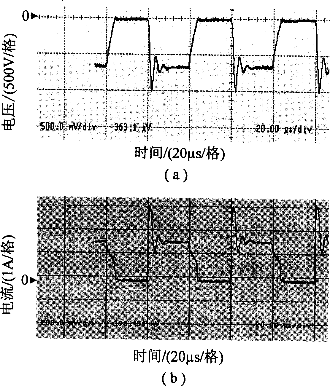
[0032] Because arc ion plating is an important technical approach of contemporary thin film technology, its application range is very wide, and arc ion plating load is actually a kind of plasma load, so here we take the matching between pulse power supply and arc ion plating load as an example (Note : In the arc ion plating process, it is necessary to apply a negative DC bias voltage or pulse bias voltage to the substrate, and the current trend is to replace the DC bias voltage applied to the substrate with pulse bias voltage), a detailed description of a pulse power supply and plasma A method for matching between body loads.

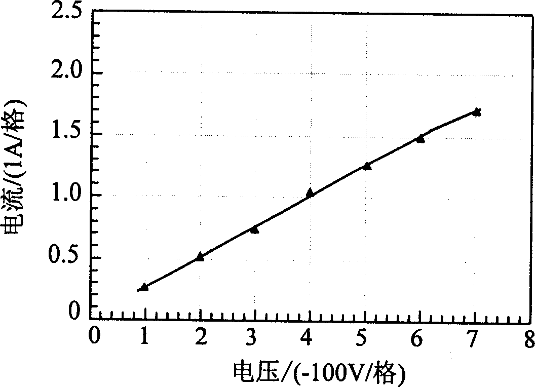
[0033] According to the voltage and current waveforms on the arc ion plating load under the pulse bias measured in the actual process (such as figure 1 shown) and the relationship between voltage an...


PUM


Abstract

The invention uses circuit theory, measurement technology, and simulation technology to design a matching circuit between pulse power and load of plasma plant. It features following point: through test, gets the voltage on load of plasma plant under the pulse voltage, current waveform and relation between voltage and current of load of plasma under the DC voltage; uses simulation technology to acquire the equivalent parameters of load of plasma plant; changes the circuit structure and simulation parameters of the matching circuit; makes the ratio (U1:U2) of the pulse voltage (U1) on load of plasma plant to the pulse voltage (U2) outputted from pulse power in effective spectral range close to the frequency response in undistorted system, and by which determines the circuit structure and the parameters.

Description

technical field [0001] The invention belongs to the technical field of electrical engineering, and in particular relates to a method for realizing the matching between a pulse power supply and a plasma load. Background technique [0002] In recent years, with the rapid development of pulse power technology, pulse power has been widely used in many fields such as material surface modification, mechanical processing, and environmental governance, and plays an important role. For example, pulse power is used in arc ion plating, electrical processing , ozone generator, etc. In these applications, the load of the pulse power supply is mostly a plasma load. In order to improve the application effect of the pulse power supply, it is generally required to match the pulse power supply and the plasma load so that the pulse voltage on the plasma load has no oscillation and a rising rate as much as possible. high. But different from other loads, plasma load has the characteristics of ...

Claims


Application Information

Patent Timeline
Patent Type & Authority Applications(China)
IPC IPC(8): H05H1/00H03H7/38
Inventor 戚栋王宁会吴彦
Owner DALIAN UNIV OF TECH
Why Eureka
Try Eureka