Method of atmospheric pressure plane discharge chemical gaseous phase depositing nano-particular film and its device

A chemical vapor deposition, atmospheric pressure technology, applied in gaseous chemical plating, metal material coating process, coating and other directions, can solve the problems of limited adjustment range, inability to achieve film structure transformation, damage to the surface of the substrate, etc. The effect of improving uniformity

Inactive Publication Date: 2006-06-14
DONGHUA UNIV
View PDF2 Cites 8 Cited by
  • Summary
  • Abstract
  • Description
  • Claims
  • Application Information

AI Technical Summary

Problems solved by technology

The main problem of the above-mentioned first method is that the glow discharge can only be generated in a small electrode gap (less than 5mm) under atmospheric pressure, and the gas and power parameters of the glow discharge allow a very limited range of adjustment. The above conditions With a slight change, the atmospheric pressure glow discharge will transform into a streamer discharge and may damage the surface of the substrate
In addition, since the gas flows through the discharge area from one side of the discharge area, the particle diameter of the film layer on the surface of the substrate and the distribution of the film layer components along the gas flow direction are not uniform.
At present, atmospheric pressure glow discharge-induced chemical vapor deposition is limited to small devices in the laboratory, and the research on the discharge mechanism and the deposition of functional thin films is mainly carried out. The generation of large-area glow discharge and the treatment or deposition of large-area material surfaces have not been seen yet. Report on Membrane Technology
The second method is to rely on the highly excited species in the discharge gas to react with the chemical gas of the deposited film. Although the direct contact between the surface of the material and the discharge area is avoided, the collision occurs during the transport from the discharge area to the reaction area under the atmospheric pressure environment. De-excitation, the density of excited species reaching the reaction area and participating in the reaction is much lower than that of the discharge area, so the rate and energy efficiency of the deposited film are greatly reduced
The films deposited by the above two methods are generally amorphous. If there is a requirement for the crystalline state of the film (such as TiO for photocatalysis 2 ), then the substrate needs to be heated during the film deposition process, or the deposited film layer should be post-treated at a higher temperature in order to realize the film transition from amorphous to crystalline state. This process method is suitable for soft materials Depositing a nanoparticle film on the surface cannot achieve the transformation of the film structure

Method used


Image

  • Method of atmospheric pressure plane discharge chemical gaseous phase depositing nano-particular film and its device
  • Method of atmospheric pressure plane discharge chemical gaseous phase depositing nano-particular film and its device
  • Method of atmospheric pressure plane discharge chemical gaseous phase depositing nano-particular film and its device

Examples


Embodiment 1

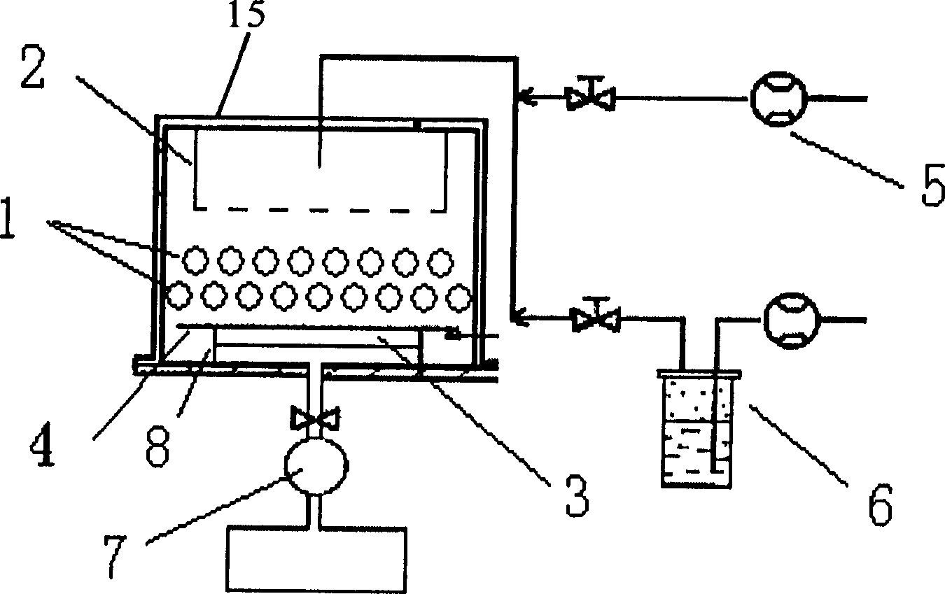
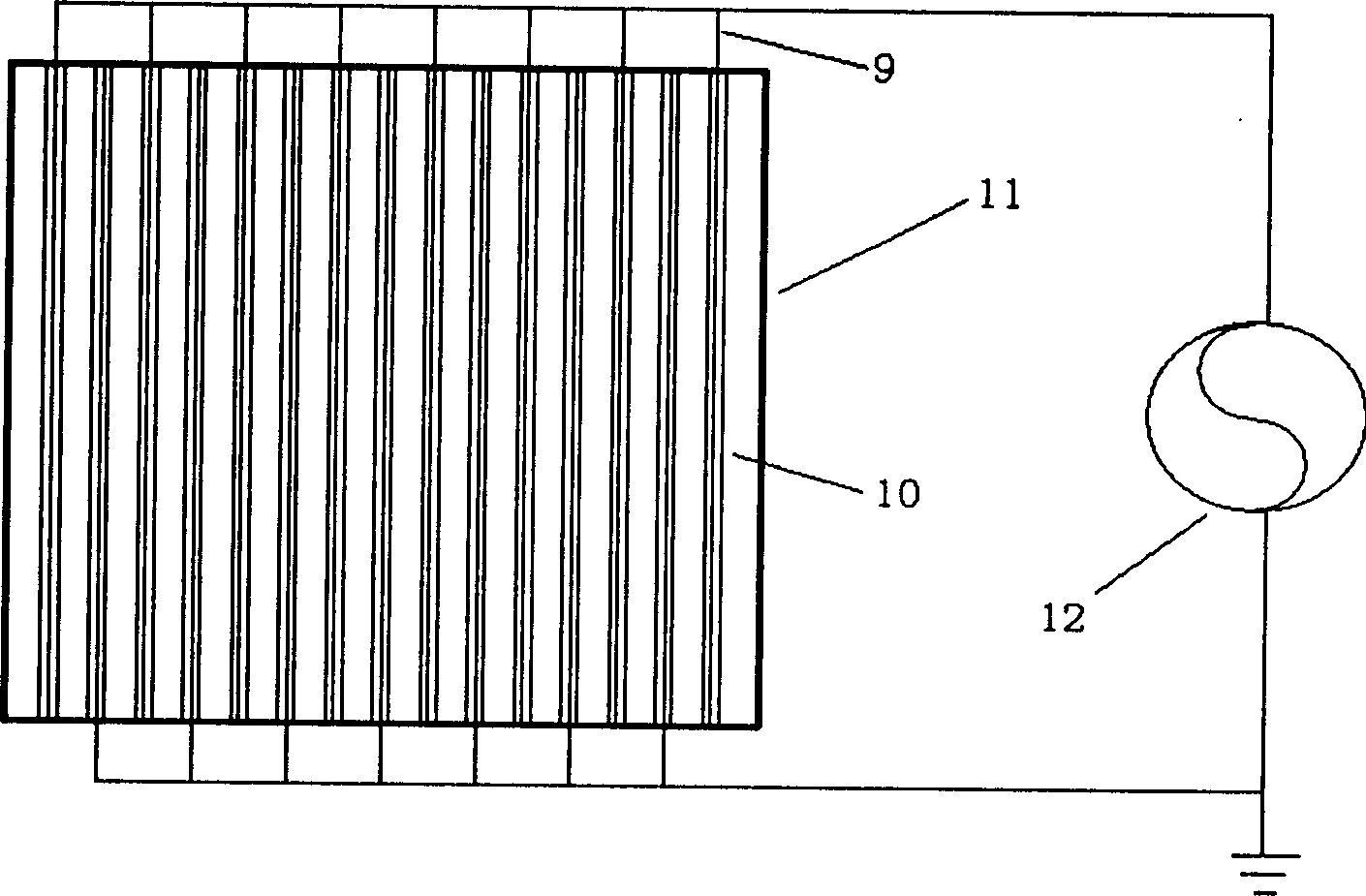
[0027] Place a planar discharge unit in the discharge area, place the cleaned substrate 4 (glass) on the metal platform 3, and use a mechanical pump 7 to vacuum the reactor to a certain extent. First, discharge auxiliary gas 5 (He, The flow rate is 1.5SLM) so that the system maintains a certain positive pressure on the gas outlet, and the high-frequency high-voltage power supply 12 (20kHz, 6.5kV) is turned on to observe the discharge state; then the volume ratio is 100:10. 4 The reaction gas 6 composed of chemical gas is passed into the reactor 15, the flow rate of the reaction gas is 100 SCCM, and the discharge appearance has obvious filamentous shape. When the discharge power is increased, the discharge appearance becomes uniform. Under the discharge power of 200W, the deposited film on the surface of the substrate is TiO nanoparticles 2 ,Such as Figure 5 Shown in (a); the distribution of the film thickness along the width of the electrode plane is as follows Figure 5 Sh...

Embodiment 2

[0029] Place the cleaned substrate 4 (cotton fabric and glass flakes for testing) on ​​the metal platform 3, use a mechanical pump 7 to vacuum the reactor 15, and first feed the discharge auxiliary gas 5 (Ar, flow rate) in the system. is 2.0SLM), then will be determined by O 4 with TiCl 4 The chemical gas is passed into the reactor 15 with the reaction gas 6 having a volume ratio of 100:5, and the flow rate of the reaction gas is 200 SCCM. Turn on the high-frequency high-voltage power supply 12, and the reaction consists of a single planar discharge unit (power is 200W, power frequency is 22kHz, voltage is 7.0kV) and two planar discharge units (power is 400W, power frequency is 17kHz, voltage is 11.0kV) When excited, the surface composition of the deposited film is as Figure 6 Shown in (a) and (b). Figure 6 (a) shows that when the thickness of the discharge area is thin (single planar discharge unit), the gas reaction is not sufficient, and the deposited film contains Cl ...

Embodiment 3

[0031] A planar discharge unit is placed in the discharge area, the cleaned substrate (glass) is placed on the metal platform 3, and the reactor 15 is vacuumed to a certain extent with the mechanical pump 7, and the discharge auxiliary gas 5 (He, The flow rate is 0.5SLM) so that the system maintains a certain positive pressure on the air outlet, and the high-frequency high-voltage power supply 12 (20kHz, 8.0kV) is turned on, and then the O 2 with TiCl 4 The chemical gas is passed into the reactor 15 in the reaction gas 6 with a volume ratio of 100:10, and the flow rate of the reaction gas is 50 SCCM. Connect the metal plate of the air distributor 2 and the metal platform 3 to the positive and negative poles of the electrostatic high-voltage power supply respectively, that is, add an electrostatic high-voltage field in the direction of gas transportation, adjust the distance between the metal platform and the metal plate of the air distributor to 1.5cm, and apply static electri...


PUM

PropertyMeasurementUnit
thicknessaaaaaaaaaa
diameteraaaaaaaaaa

Abstract

The invention relates to an atmosphere pressure plane discharging chemical vapor deposition nanometer membrane granulose method and equipment. Its features are setting airflow divider in the reactor to make airflow uniformly flow through the discharging area and form film; setting different plane discharging unit in the reactor, increasing and reducing the cross distance to adjust deposited film component, and form crystalline state film; applying static high-voltage field to adjust forming predecessor and spatial configuration to adjust and control the film growth appearance.

Description

technical field [0001] The invention relates to an atmospheric pressure gas discharge plasma-enhanced chemical vapor deposition (AP-PECVD) film method, in particular to an atmospheric pressure plane discharge method that uniformly deposits the same composition on the surface of various materials including soft materials and has certain crystallization characteristics Nanoparticle film method and device. Background technique [0002] Low-pressure gas discharge non-equilibrium plasma technology has a very mature application in material surface treatment and thin film preparation, but if the process of continuous treatment or deposition is realized on the surface of materials such as polymers, fabrics and paper, it requires a large volume of manufacturing Vacuum chamber or tunnel kiln system with graded pre-vacuum and high vacuum, which brings great inconvenience to this type of application and greatly increases the process cost; Atmospheric pressure gas discharge non-equilibri...

Claims


Application Information

Patent Timeline
Patent Type & Authority Applications(China)
IPC IPC(8): C23C16/513
Inventor 徐金洲徐绍魁周荃彭小波张菁
Owner DONGHUA UNIV
Why Eureka
Try Eureka