
Self-adaptive method of intelligent antenna for forming wave packet and demodulating data

An adaptive beam and smart antenna technology, applied in antennas, antenna arrays, diversity/multi-antenna systems, etc., can solve the problems of complex implementation of adaptive smart antennas, avoid non-convergence problems, facilitate engineering implementation, and improve overall performance and the effect of the scope of application

Inactive Publication Date: 2006-07-05
晋江市高新技术开发办公室
View PDF2 Cites 5 Cited by
  • Summary
  • Abstract
  • Description
  • Claims
  • Application Information

AI Technical Summary

Problems solved by technology

[0006] The purpose of the present invention is to overcome the shortcomings of the above-mentioned smart antenna system, solve the complex problem of adaptive smart antenna implementation, and propose a simple and effective smart antenna adaptive beamforming method

Method used


Image

  • Self-adaptive method of intelligent antenna for forming wave packet and demodulating data
  • Self-adaptive method of intelligent antenna for forming wave packet and demodulating data
  • Self-adaptive method of intelligent antenna for forming wave packet and demodulating data

Examples


Embodiment Construction

[0034] The implementation of the technical solution will be further described in detail below in conjunction with the accompanying drawings. According to these flow charts and structural diagrams, those skilled in the same field can easily realize these modules.

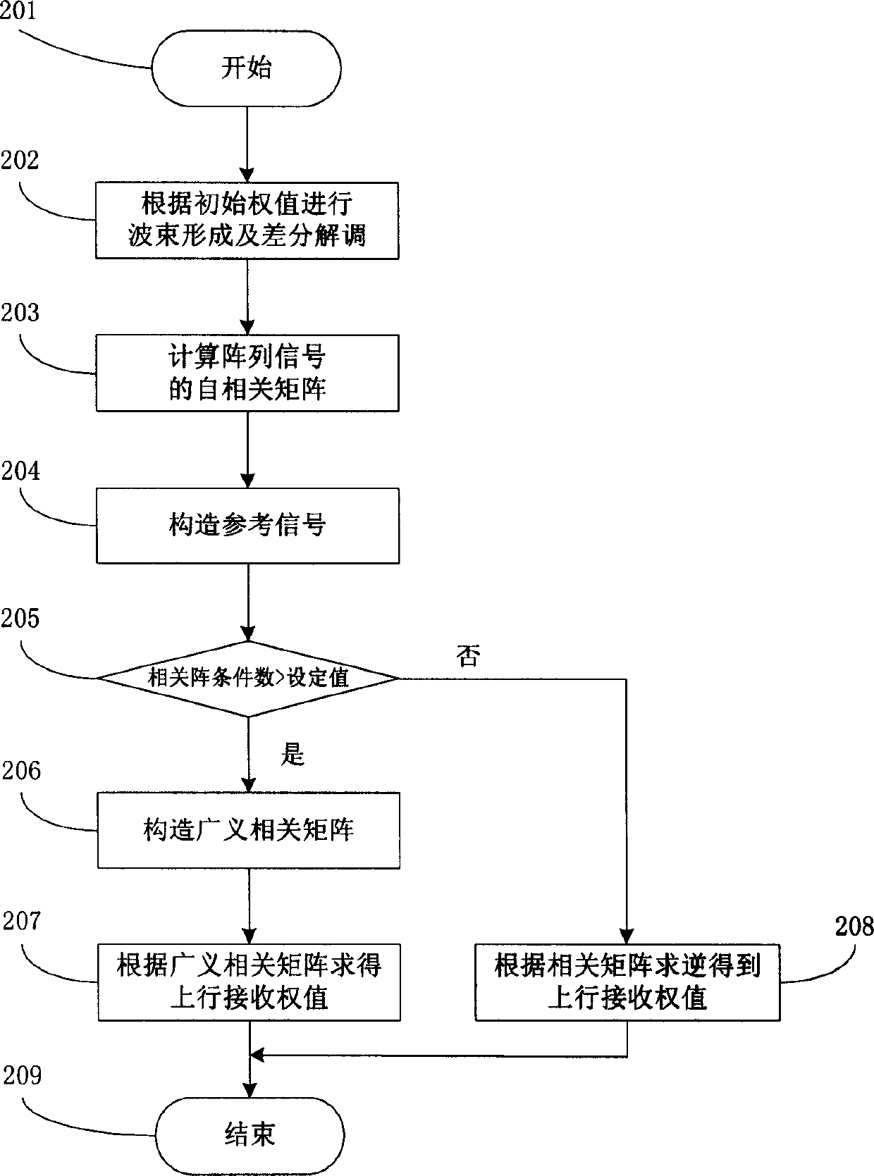
[0035] figure 1 It is a flow chart of the adaptive beamforming method of the present invention. In the adaptive smart antenna, the weights corresponding to the air domain or the air and time domain processing can be adjusted arbitrarily according to a certain adaptive algorithm to match the current transmission environment as much as possible, and the corresponding smart antenna receiving / transmitting beams can be is arbitrary. In practice, because the algorithm is often very complex, it is more difficult to realize. Therefore, the starting point of the present invention is to optimize the system structure and reduce the calculation amount of the algorithm. The method described in the present invention can be real...


PUM


Abstract

The invention includes steps: using approximate solution of minimum mean square error instead of Wiener solution as an initial value; according to above basis, estimating noise power, and determining value of delta2; constructing broad sensing correlation matrix XíñXH+ delta2I; further, using Wiener solution obtains weight value Wú¢(XíñXH+delta2I) -1íñXíñdH. Advantages of the invention are: avoiding instability of weight value caused by singular matrices, extending algorithm applicability of intelligent antenna, and simplifying system structure, raising operation speed, tracking userí»s quick moving in real time, and resisting multiple interferences. Comparing with prior art, the invention overcomes disadvantages of large quantity of calculation, complex structure of system etc.

Description

technical field [0001] The invention relates to the technical field of receiving / transmitting smart antennas in digital wireless communication, in particular to a PHS system (Personal Handy-phone System) smart antenna base station adaptive beam forming and data demodulation method. Background technique [0002] In the field of mobile communication in recent years, the application of smart antenna technology for the purpose of effective use of frequency and improvement of communication quality has attracted more and more attention. The so-called smart antenna technology uses more than two single-antenna array elements to form an antenna array. The signal received by each array element is weighted and summed with an appropriate weight after radio frequency processing, which can achieve the effect of directional reception. A weight vector Corresponding to a certain beam pattern. The essence of weighting is a kind of spatial filtering, and the smart antenna can also be regarded...

Claims


Application Information

Patent Timeline
IPC IPC(8): H04B7/04H04Q7/36H01Q21/00
Inventor 王衍文许航
Owner 晋江市高新技术开发办公室
Learn More