Programmable logic control device for automobile transmission case with manual gearshift

A technology of programming logic control, automobile gearbox, applied in the direction of transmission control, components with teeth, belt/chain/gear, etc. Incorrect shifting and other problems, to achieve the effect of low design and manufacturing cost, superior anti-interference performance and high integration

Inactive Publication Date: 2006-07-19
SOUTH CHINA UNIV OF TECH
View PDF0 Cites 8 Cited by
  • Summary
  • Abstract
  • Description
  • Claims
  • Application Information

AI Technical Summary

Problems solved by technology

The disadvantage of the above-mentioned mechanical shifting is that when using the handle to push the manual hydraulic shifting valve, it generally requires about 30N of force, and the labor intensity of the driver's hand is very high.
[0004] At present, there are also a small number of gearbox electronic control devices designed for this type of rear engine using a general-purpose single-chip microcomputer (such as MCS51, etc.), but experiments have shown that the gearbox electronic control device designed with a single-chip microcomputer uses a single-chip microcomputer. The working environment of the electronic control device is relatively harsh. In addition, the single-chip microcomputer runs through the program. The bad working environment will easily cause the single-chip microcomputer to be disturbed and the program will run away. This phenomenon will lead to incorrect gear shifting. It is absolutely not allowed to have incorrect gear shifting in a car, because if the gear shifting is incorrect, it will cause damage to mechanical devices such as gearbox gears, and it will cause serious traffic accidents if it is serious.

Method used


Image

  • Programmable logic control device for automobile transmission case with manual gearshift
  • Programmable logic control device for automobile transmission case with manual gearshift
  • Programmable logic control device for automobile transmission case with manual gearshift

Examples


Embodiment 1

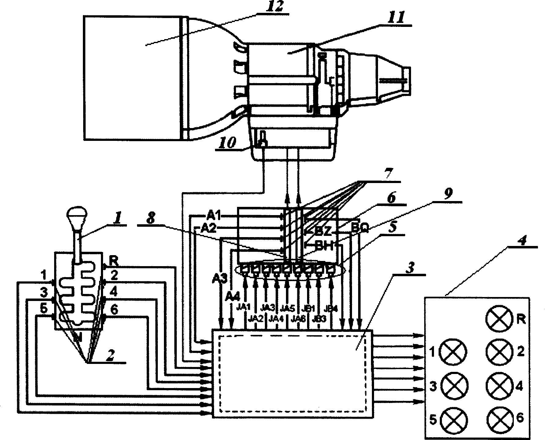
[0055] Such as figure 1 As shown, the gearbox control device of the manual shift vehicle includes a shift lever 1, a gear switch sensor 2, a CPLD main control module 3, an electronically controlled reversing valve 6, an A cylinder 8, a B cylinder 9, and a cylinder in place The switch sensor 7 and the gear switch sensor 2 are installed at the 1, 2, 3, 4, 5, 6, N, and R gears of the base of the automobile shift lever 1, the gear switch sensor 2, and the cylinder in-position switch sensor 7 They respectively include return spring, spring leaf, and contact. One end of the contact is connected to the power supply, and the other end is connected to the CPLD main control module 3. When the shift lever 1 is moved to any gear position, the corresponding gear switch sensor 2 is immediately sucked. close, the power signal is transmitted to the CPLD main control module 3 through the contact of the pull-in, and the 9 drive coils 5 (JA1, JA2, JA3, JA4, JA5, JA6, JA4, JA5, JA6, JB1, JB3, JB...

Embodiment 2

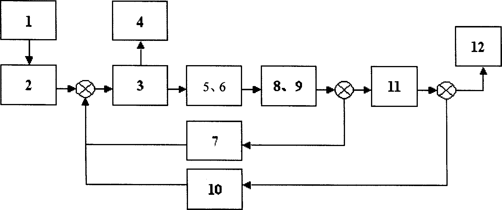
[0058] When shifting from neutral N to first gear, if figure 1 , 2 , Shown in 3, the shift control step of this device is:

[0059] (1) The driver depresses the clutch, pushes the shift lever 1 from the N gear to the 1st gear, the contact of the gear switch sensor 2 of the 1st gear is closed, and the gear position signal is transmitted to the CPLD main control module 3;

[0060] (2) According to the gear position signal of the gear switch sensor 2 and the vehicle speed signal of the vehicle speed sensor 10, the CPLD main control module 3 judges that the shift intention is 1st gear, which is valid, and then the CPLD main control module 3 outputs the gear position signal to the gear position in real time The display circuit 4 realizes the real-time display of the gear position. Because it is an advanced gear, and according to Table 1 and Table 2, the CPLD main control module 3 first outputs the drive signal of 24V to the corresponding drive coil 5 of the A cylinder 8, that is, ...

Embodiment 3

[0063] When shifting from 3rd gear to N gear, if figure 1 , 2 , Shown in 3, the shift control step of this device is:

[0064] (1) The driver depresses the clutch and pushes the shift lever 1 from the 3rd gear to the N gear. At this time, the contacts of the 1, 2, 3, 4, 5, 6 and R gear switch sensor 2 all bounce off;

[0065] (2) According to the state that all the contacts of the gear switch sensor of 1, 2, 3, 4, 5, 6 and R are bounced off and the vehicle speed signal of the vehicle speed sensor 10, the CPLD main control module 3 judges that the shifting intention is the N gear , effective, then the CPLD main control module 3 outputs signals to the stall real-time display circuit 4 to realize the real-time display of the stalls, because it is out of gear, and according to Table 1 and Table 2, the CPLD main control module 3 first outputs the drive signal of 24V to the The corresponding driving coil 5 of the B cylinder 9, that is, energizes the driving coils JB1 and JB4 to dr...


PUM


Abstract

The invention provides a programmable logic control device of hand-operated shift vehicle speed change box, which comprises a shift operation rod, a switch sensor, a CPLD main control module, an electric control shift valve, the A cylinder and the B cylinder. Wherein, the switch sensor comprises stage switch sensors and cylinder positioned switch sensors, while the stage switch sensors are mounted at the each stage of vehicle shift operation rod base to connect the power resource and the CPLD main control module; the CPLD main control module is connected to the drive coil of electric control shift valve; the electric control shift valve is connected to the A cylinder and the B cylinder; the A and B cylinders are individually connected to the speed change gear device of speed change box; the cylinder positioned switch sensors are mounted at the outer walls of A cylinder and B cylinder to connect the power resource and the CPLD main control module; the speed sensor is mounted inside the speed change box to connect the CPLD main control module. The invention uses the 7064S CPLD in MAXII system of Altera Company as the main control module which has simple structure, easy operation, high control speed, stable operation and stronger anti-disturb ability.

Description

technical field [0001] The invention relates to automobile gearbox equipment, in particular to a programmable logic control device and a shift control method for a manual shift automobile gearbox. Background technique [0002] Existing trucks such as buses, coaches and commercial trucks, due to their flat-top car structure, have established conditions for installing the transmission in space, that is, the transmission must be moved to a place far away from the driver's seat, especially when When the car has an engine under the compartment or a rear engine, the distance between the transmission and the driver's seat is relatively long, and in the transmission with mechanical shifting, the structure of the shift lever system is complicated, the power transmission distance is long, and it is difficult to shift gears accurately. The inter-stress effect is large, and the mutual wear is also large. [0003] The gear shift control of the domestic hydraulic...

Claims


Application Information

Patent Timeline
Patent Type & Authority Applications(China)
IPC IPC(8): F16H61/02
Inventor 钟汉如卞健勇
Owner SOUTH CHINA UNIV OF TECH
Why Eureka
Try Eureka