
Inlaying-combination type oil sprayer

A fuel injector and combined technology, applied in the direction of machines/engines, fuel injection devices, engine components, etc., can solve problems such as increased fuel consumption, decreased fuel atomization quality, and affecting normal operation of the engine to achieve fuel saving, The effect of precise control of oil intake and simple structure

Inactive Publication Date: 2006-08-09
SOUTHWEST UNIVERSITY
View PDF0 Cites 4 Cited by
  • Summary
  • Abstract
  • Description
  • Claims
  • Application Information

AI Technical Summary

Problems solved by technology

In addition, the existing fuel injector itself does not have the function of pressure regulation. With the prolongation of the running time of the vehicle, the fuel injection pressure of the fuel injector will gradually decrease. Accurate, it will inevitably reduce the quality of fuel atomization and increase fuel consumption, which will affect the normal operation of the engine

Method used


Image

  • Inlaying-combination type oil sprayer
  • Inlaying-combination type oil sprayer
  • Inlaying-combination type oil sprayer

Examples


Embodiment 1

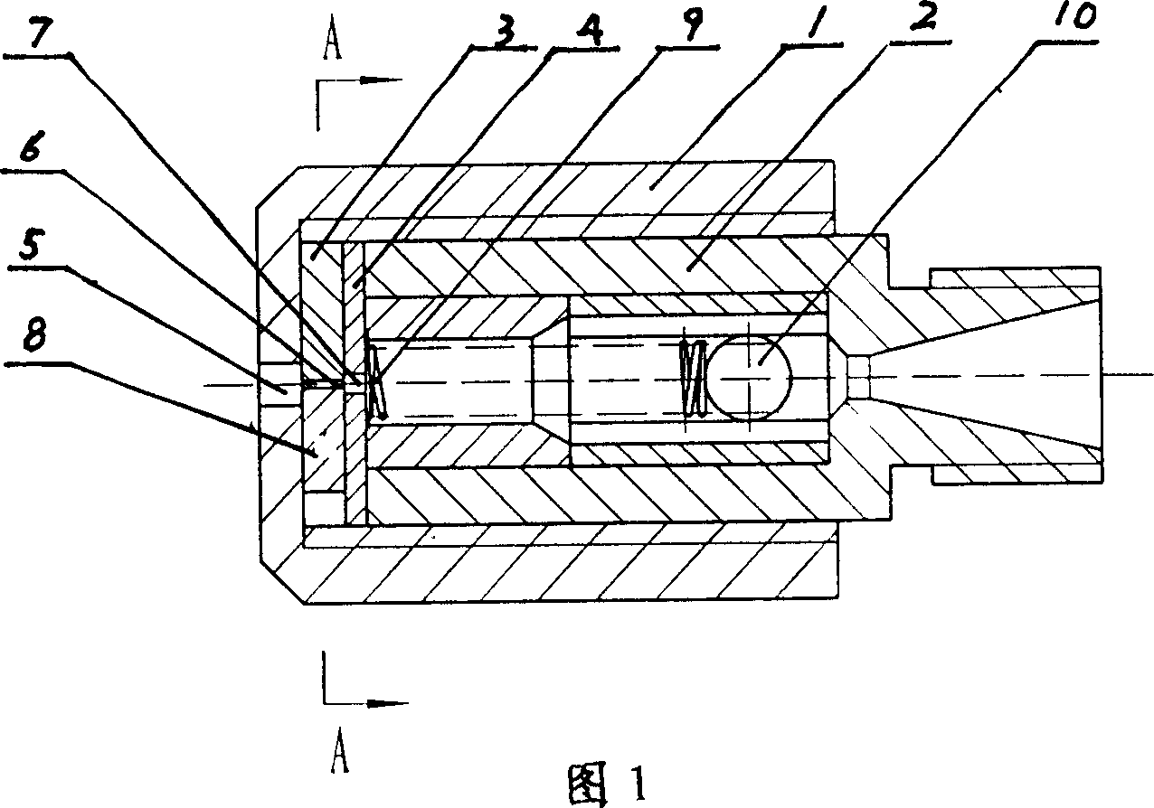
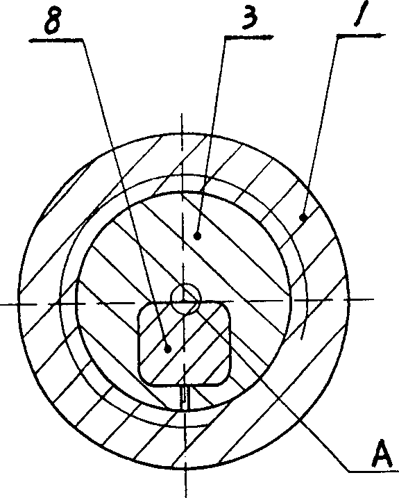
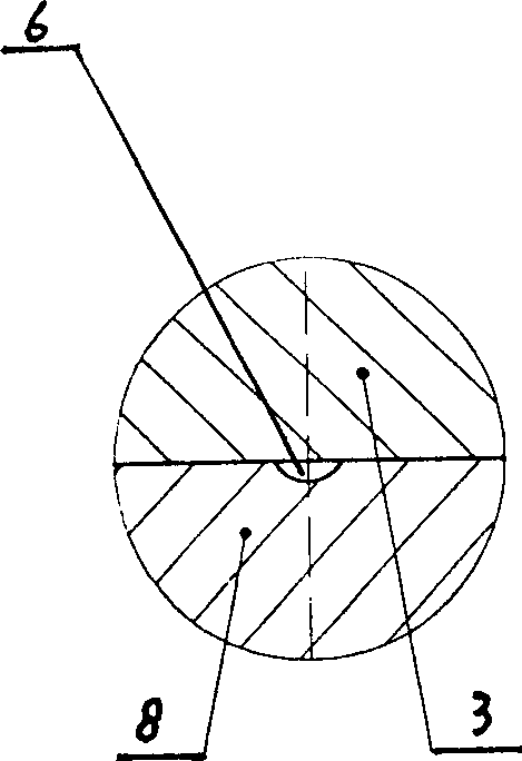
[0028] Embodiment one: the first scheme of the present invention. Referring to Fig. 1, Fig. 2 and Fig. 3, the steel ball 10 is installed in the oil inlet of the check valve 2, and one end of the compression spring 9 is close to the steel ball 10; a square restrictor plate 8 is embedded in the In the middle of the orifice plate 3, there is a micro gap between the orifice plate and the limiting plate, which is the injection hole 6; the limiting plate, the orifice plate and the injection hole can be cut by wire cutting machine processing;

[0029] Referring to Fig. 1, put the orifice plate 3 and the partition plate 4 inlaid with the flow limiting plate 8 into the casing 1, and connect the check valve 2 with the casing, and the orifice plate 3 and the partition plate 4 are located on the inner end surface of the casing Between and the front end of the one-way valve, the oil outlet 5 at the end of the jacket is opposite to the oil injection hole 6 on the orifice plate, and the oil...

Embodiment 2

[0031] Embodiment two: the second scheme of the present invention. see Figure 12 As shown in Fig. 15, the orifice plate 3 and the partition plate 4 embedded with the flow limiting plate 8 are put into the casing 1, and the one-way valve 2 is connected with the casing, and the orifice plate 3 and the partition plate 4 are located on the inner end surface of the casing Between and the front end of the one-way valve, the oil outlet 5 at the end of the jacket is opposite to the oil injection hole 6 on the orifice plate, and the oil injection hole on the orifice plate is opposite to the oil passage hole 7 on the separator, and the separator The oil hole on the top communicates with the one-way valve, and the other end of the compression spring 9 installed in the one-way valve is close to the separator 4; one end of the oil inlet of the one-way valve 2 is processed to be perpendicular to the oil inlet passage. A square hole 11, a pressure regulating seat 13 is installed in the squ...


PUM


Abstract

Present invention relates to an embedded unit injector including outer case, one-way valve, jet orifice plate and partition. It features in middle of jet orifice plate at least embedded a piece of restrictor plate, at least a micro interstice set between jet orifice plate and restrictor plate, said micro interstice is fuel injection hole, outer case oil outlet opposite with jet orifice plate fuel injection hole, jet orifice plate fuel injection hole opposite with partition through fuel hole, partition through fuel hole opposite with one-way valve. Said invention also refers to a embedded unit injector, one end in one-way valve oil inlet set with square opening vertical with fuel inlet channel, one end of one-way valve oil inlet vertical connected with valve body of oil pressure adjusting valve, square opening located upper of said communicated with oil pressure adjusting valve. It has simple structure, convenient for manufacture, precision controlling fuel feed, saving fuel, in time adjusting fuel injection pressure, raising fuel atomization quality.

Description

technical field [0001] The invention relates to an automobile fuel injector, in particular to a mosaic combined fuel injector. Background technique [0002] In the past 20 years, in order to meet the increasingly stringent requirements of automobile emission regulations, some countries have adopted a mixture formation system that directly injects gasoline into the intake pipe, that is, the electronically controlled injector is installed at the air intake of the engine, and is controlled by the electronic control unit. control, successfully replacing carburetor feed systems, and is increasingly being used in passenger car and light vehicle engines. Although the method of directly injecting gasoline into the engine intake pipe has many advantages, after the 1960s, the electronically controlled gasoline injection system was installed on the car engine and put into practice. But there are still many deficiencies. The fuel injector of its fuel supply part is the most important ...

Claims


Application Information

Patent Timeline
IPC IPC(8): F02M61/18
Inventor 薛荣生林毓培刘伟
Owner SOUTHWEST UNIVERSITY
Learn More