Illumination system

A lighting system, optically transparent technology, applied in the field of lighting systems, can solve problems such as uncontrollable, and achieve the effect of not being damaged and polluted

Inactive Publication Date: 2006-08-09
KONINKLIJKE PHILIPS ELECTRONICS NV
View PDF1 Cites 2 Cited by
  • Summary
  • Abstract
  • Description
  • Claims
  • Application Information

AI Technical Summary

Problems solved by technology

In prior art lighting systems, as described in WO 01 / 51849, the direction of outcoupled polarized light is fixed and cannot be controlled

Method used


Image

  • Illumination system
  • Illumination system
  • Illumination system

Examples


Embodiment Construction

[0044] Detailed Description of Preferred Embodiments

[0045] In the following description, "birefringence" means that a transparent object has one index of refraction, the ordinary index of refraction, for light of a first polarization and another index of refraction for light of a second polarization opposite to said first polarization , that is, the abnormal refractive index. Materials that exhibit birefringence are said to be "anisotropic". A material that has the same index of refraction regardless of the polarization of the light is said to be "isotropic".

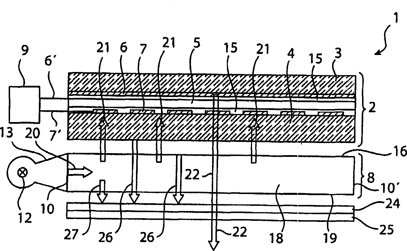
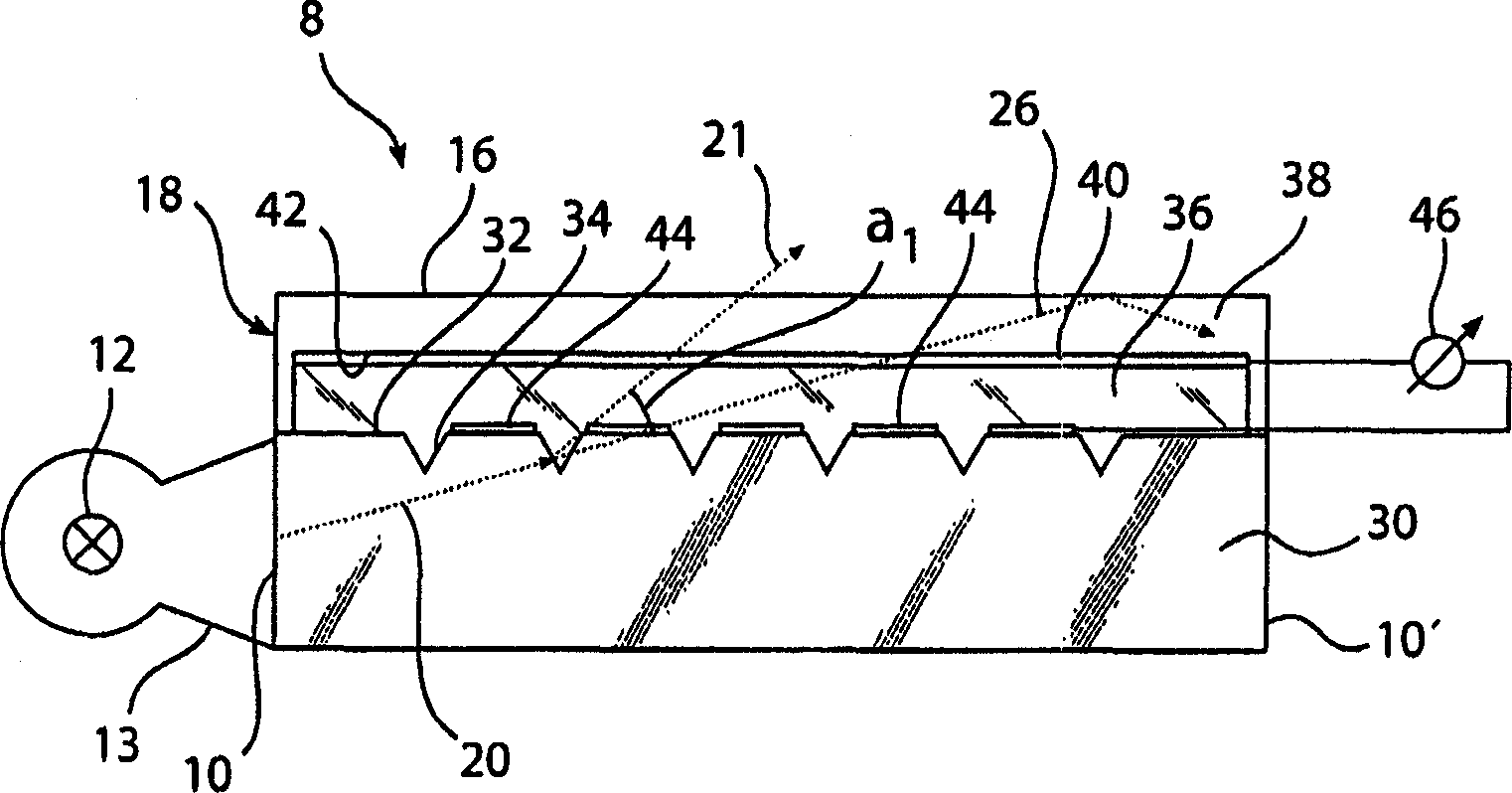
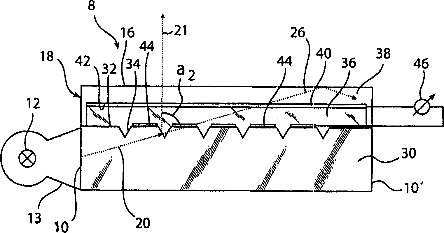
[0046] figure 1The display device 1 schematically shown in FIG. 2 comprises an image display panel 2 and an illumination system 8 positioned between a viewer (not shown) and the display panel 2 , thereby providing frontal illumination of the display panel 2 .

[0047] The picture display panel 2 comprises a liquid crystal material 5 located between two substrates 3, 4, based on a twisted nematic (TN), supertwisted...


PUM


Abstract

An illumination system (8) comprises an optical waveguide (18) which is made from optically transparent components and has four end faces (10, 10'). A light source (12) whose light is coupled into the optical waveguide (18) via one of the end faces (10) is situated opposite this end face (10). The optical waveguide (18) has a light guide (30). A birefringent layer (36) comprising liquid crystals is provided on the light guide (30) at an exit surface side thereof. A first electrode (40) and a second electrode (44) both have electrical contact with the birefringent layer (36) and are connected to a voltage generator (46). By varying the voltage applied between the electrodes (40, 44), the birefringent properties of the birefringent layer (36) comprising the liquid crystals may be varied to control the direction of light coupled out via the exit surface (16).

Description

field of invention [0001] The invention relates to an illumination system comprising an optical waveguide which is optically transparent and has an exit surface and a number of end faces, a light source is located opposite at least one end face, at which light from the light source is coupled into In the optical waveguide, the optical waveguide has a polarization device integrated therein for polarizing the light emitted by the light source. [0002] The invention further relates to a method of manufacturing a polarizing device in an optical waveguide, the optical waveguide being optically transparent and having an exit surface and a plurality of end faces, a light source being located opposite at least one end face, light from the light source being in said at least one Coupled into the optical waveguide at the end face, the polarizing means is adapted to polarize the light emitted by the light source. [0003] The invention also relates to a method of controlling the direct...

Claims


Application Information

Patent Timeline
Patent Type & Authority Applications(China)
IPC IPC(8): G02F1/13357G02F1/1335F21V14/00
CPCH04M1/22F21V14/003G02F2001/133616G02B6/0038F21S48/1731G02B6/0056G02F1/13362F21S41/645G02F1/133616G02F1/1335
Inventor H·P·M·胡克
Owner KONINKLIJKE PHILIPS ELECTRONICS NV
Why Eureka
Try Eureka