Semi-automatic underwater welder with local dryness

A local dry and underwater welding technology, which is applied in welding equipment, welding accessories, arc welding equipment, etc., can solve problems such as arc instability, poor mechanical properties of welded joints, and poor weld formation, achieving low cost, Strong adaptability to operation and high welding quality

Inactive Publication Date: 2006-08-16
SOUTH CHINA UNIV OF TECH
View PDF0 Cites 15 Cited by
  • Summary
  • Abstract
  • Description
  • Claims
  • Application Information

AI Technical Summary

Problems solved by technology

The weld seam quality of this method is very good, and the equipment is much simpler than the dry method. The disadvantage is that the construction operation ship has to carry more CO 2 Gas, and the drainage cover is too large, the operation is inconvenient, so that some underwater s

Method used


Image

  • Semi-automatic underwater welder with local dryness
  • Semi-automatic underwater welder with local dryness
  • Semi-automatic underwater welder with local dryness

Examples


Embodiment Construction

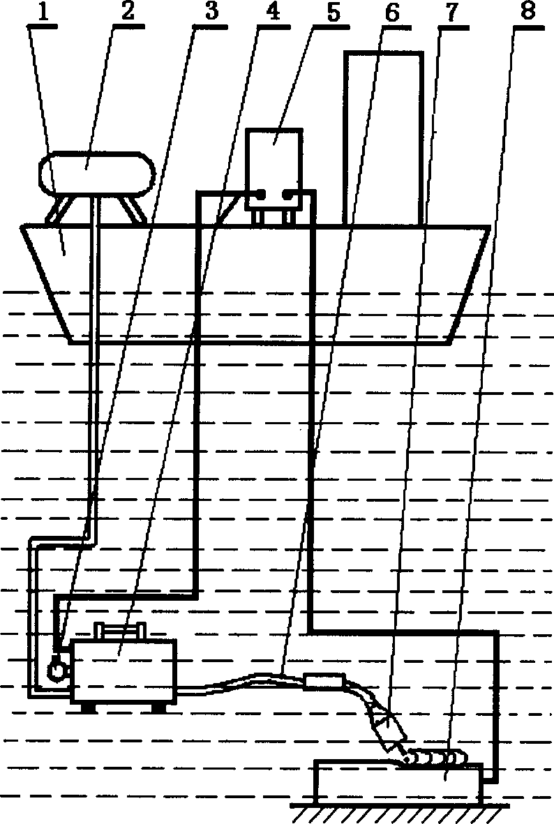
[0017] Depend on figure 1 It can be seen that in the semi-automatic partial dry underwater welding device of the present invention, the compressed air produced by the air compressor 2 communicates with the underwater wire feed box 4 through the pipeline; the special welding power supply 5 is connected with the underwater wire feed box 4 through cables; The lower wire feeding box 4 is connected with the welding torch 6 through the wire guide tube, and the miniature drainage cover 7 is installed at the end of the welding torch.

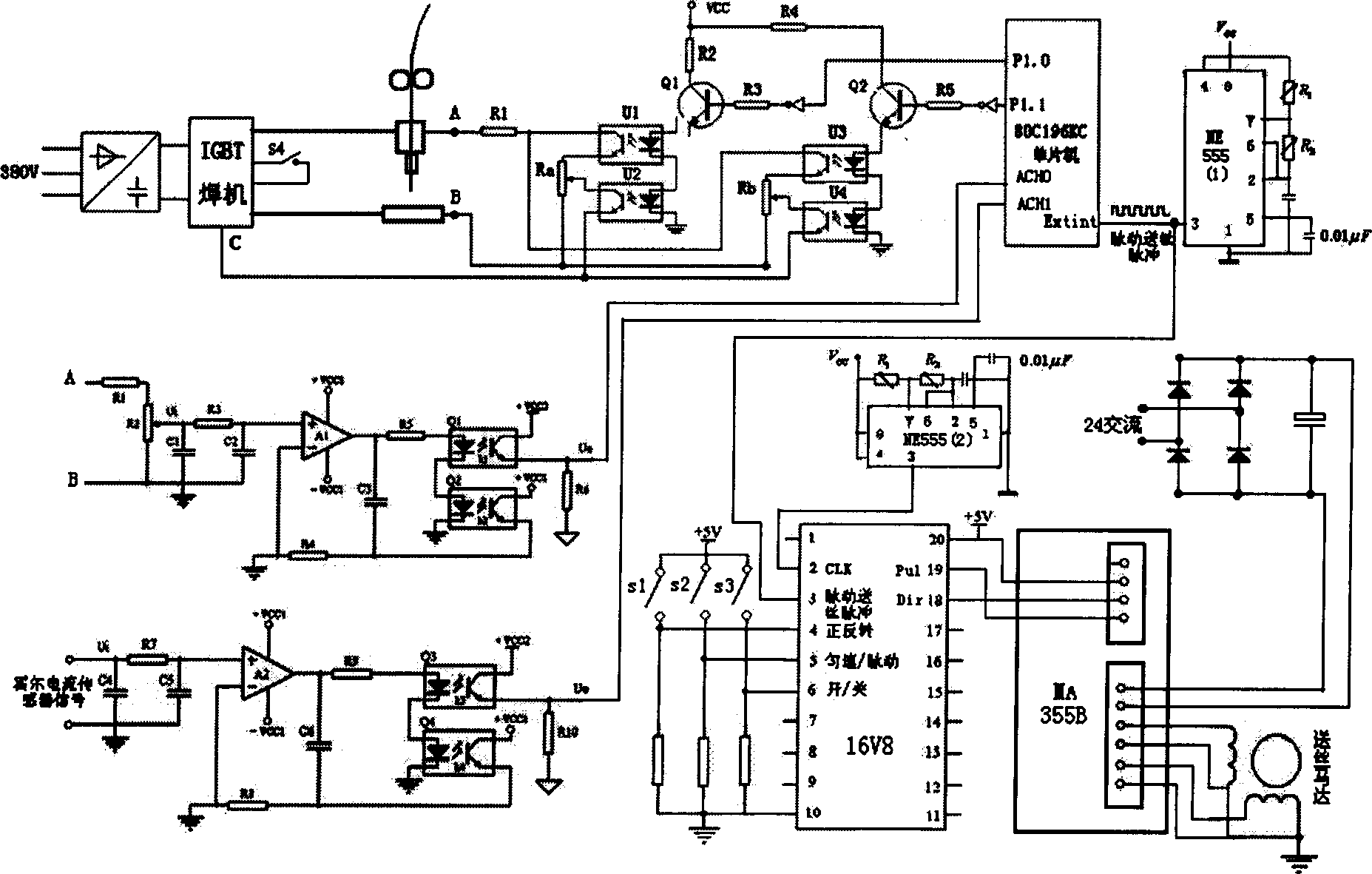
[0018] figure 2 It is a circuit diagram of a special welding power supply (including a pulsating wire feeding system) of the new semi-automatic partial dry underwater welding device of the present invention. After the system is powered on, figure 2 The NE555(2) in it generates a clock pulse with a frequency of about 10 kHz, which is used to drive the stepper motor to rotate, and the NE555(1) generates a pulsating wire-feeding pulse with a frequency ...


PUM


Abstract

A semi-automatic underwater welder with local drying method is composed of job ship, air compressor on the ship, welding power supply, underwater wire feeding case connected to said welding power supply via cable, welding gun linked to said wire feeding case via wire guiding tube, and miniature water rejecting hood on the front end of welding gun.

Description

technical field [0001] The invention relates to the field of underwater welding, in particular to a semi-automatic partial dry underwater welding device. technical background [0002] Underwater welding is one of the key technologies in marine engineering construction (including construction of offshore oil platforms and submarine oil and gas pipelines, emergency maintenance of ships at sea, etc.). With the increasing number of marine engineering projects in our country, higher requirements are put forward for the quality, efficiency, cost and operability of underwater welding. Foreign underwater welding of important structures all adopts dry welding. The method is to build a sealed cabin at the part to be welded and drain the water inside, so that both the welder and the arc are in a "dry" environment. The weld quality of the dry method is high, but the equipment structure is complex and expensive. [0003] Domestic Harbin Welding Research Institute has studied CO 2 Gas ...

Claims


Application Information

Patent Timeline
IPC IPC(8): B23K9/00B23K9/133B23K9/09B23K9/32
Inventor 王国荣石永华钟继光
Owner SOUTH CHINA UNIV OF TECH
Why Eureka
Try Eureka