Optical-fibre and grating acoustic transmitting and temperature sensor

A technology of temperature sensor and optical fiber grating, applied in the field of sensors, can solve problems such as fear of electromagnetic interference, inability to monitor temperature at the same time, and long signal transmission distance

Inactive Publication Date: 2006-08-16
关柏鸥
View PDF2 Cites 24 Cited by
  • Summary
  • Abstract
  • Description
  • Claims
  • Application Information

AI Technical Summary

Problems solved by technology

[0003] The purpose of the present invention is to solve the technical problems of existing acoustic emission sensors that are afraid of electromagnetic interference, unable to remotely monitor, and unable to monitor temperature at the same time, and to provide

Method used


Image

  • Optical-fibre and grating acoustic transmitting and temperature sensor
  • Optical-fibre and grating acoustic transmitting and temperature sensor
  • Optical-fibre and grating acoustic transmitting and temperature sensor

Examples


Embodiment Construction

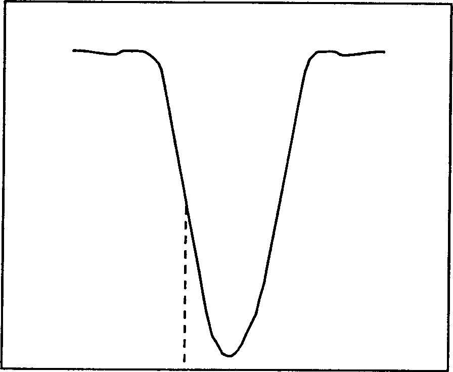
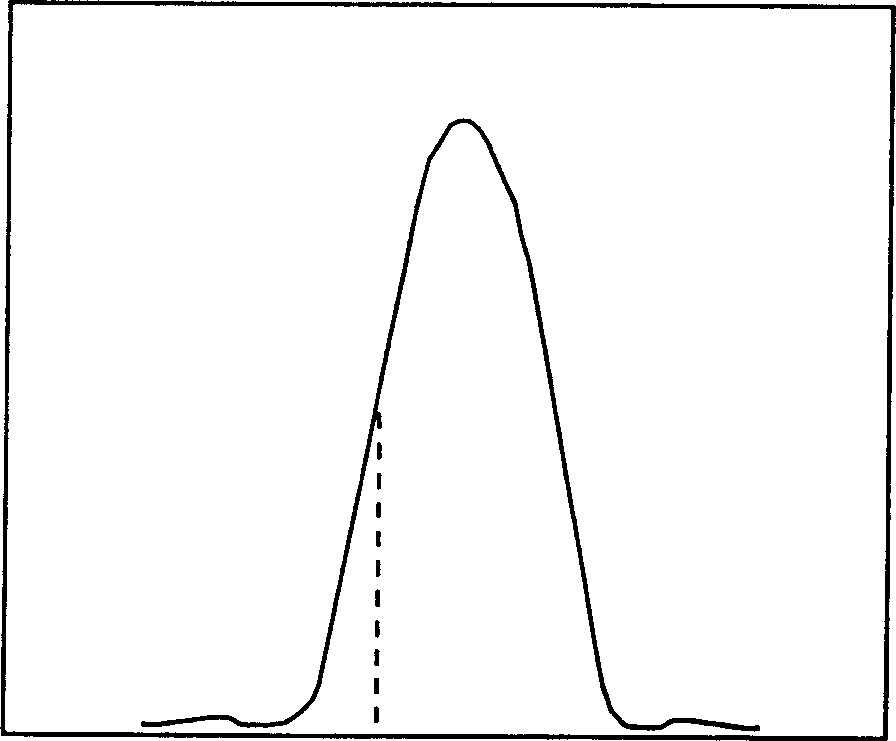
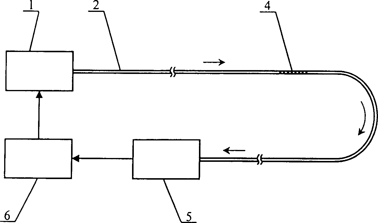
[0047] figure 2 The structure of the first embodiment of the present invention is shown, and the fiber grating acoustic emission and temperature sensor of the present embodiment includes: a laser 1 connected in sequence with an optical fiber 2, a fiber grating 4, a receiving unit 5 and the laser 1 and the laser The receiving unit 5 is electrically connected to the control unit 6 . The arrows in the figure indicate the traveling direction of the optical signal. The working wavelength of the laser 1 is located on the slope of the resonance peak of the fiber Bragg grating 4 , and its outgoing light enters the fiber Bragg grating 4 , and enters the receiving unit 5 after being transmitted by the fiber Bragg grating 4 . The receiving unit 5 converts the optical signal transmitted by the fiber grating 4 into an electrical signal, and provides feedback to the control unit 6 . The laser 1 has a manipulation parameter, the magnitude of which is controlled by the control unit 6, and ...


PUM


Abstract

A sound emission and temperature transducer of optical fiber grating is prepared as incoming an outgoing light from laser to optical fiber grating then entering it into receiving unit with light detection element to convert light signal to be electric signal as well as providing feedback to control unit, using control unit to control operation parameter variation of laser to let working wave length of laser be held at position assigned by resonance peak slope of said optical fiber grating.

Description

technical field [0001] The present invention relates to sensors, and more particularly, the present invention relates to sensors for monitoring sound waves and temperature. Background technique [0002] Acoustic emission technology is an advanced non-destructive testing technology, which obtains the internal damage, fracture, deformation and other information of the measured object by detecting and analyzing the sound waves emitted by the measured object itself. This technology is widely used in petroleum, chemical, electric power, aerospace, metal It is widely used in processing, water conservancy and hydropower and other fields. The key component of acoustic emission technology is the acoustic emission sensor that collects and detects sound waves. Existing acoustic emission sensors such as the disclosed acoustic emission sensors of Chinese patents CN101673B, CN87214610U and ZL96200752.8 are all based on piezoelectric ceramics or piezoelectric crystal materials, and their ...

Claims


Application Information

Patent Timeline
IPC IPC(8): G01N21/84G01N21/17G01H17/00G01K11/32G01K11/3206
Inventor 关柏鸥
Owner 关柏鸥
Why Eureka
Try Eureka