High-code ratio communication system between relay satellite and low-track satellite

A relay satellite and communication system technology, applied in the field of communication systems between relay satellites and low-orbit satellites, can solve the problem of low communication data rate and achieve the effect of increasing communication data rate

Inactive Publication Date: 2011-04-20
HARBIN INST OF TECH
View PDF0 Cites 0 Cited by
  • Summary
  • Abstract
  • Description
  • Claims
  • Application Information

AI Technical Summary

Problems solved by technology

[0004] The purpose of the present invention is to provide a high code rate communication system between relay satellites and low-orbit satellites, to overcome the low defect of the communication data rate of existing relay satellites and low-orbit satellite communication systems

Method used


Image

  • High-code ratio communication system between relay satellite and low-track satellite
  • High-code ratio communication system between relay satellite and low-track satellite
  • High-code ratio communication system between relay satellite and low-track satellite

Examples


specific Embodiment approach 1

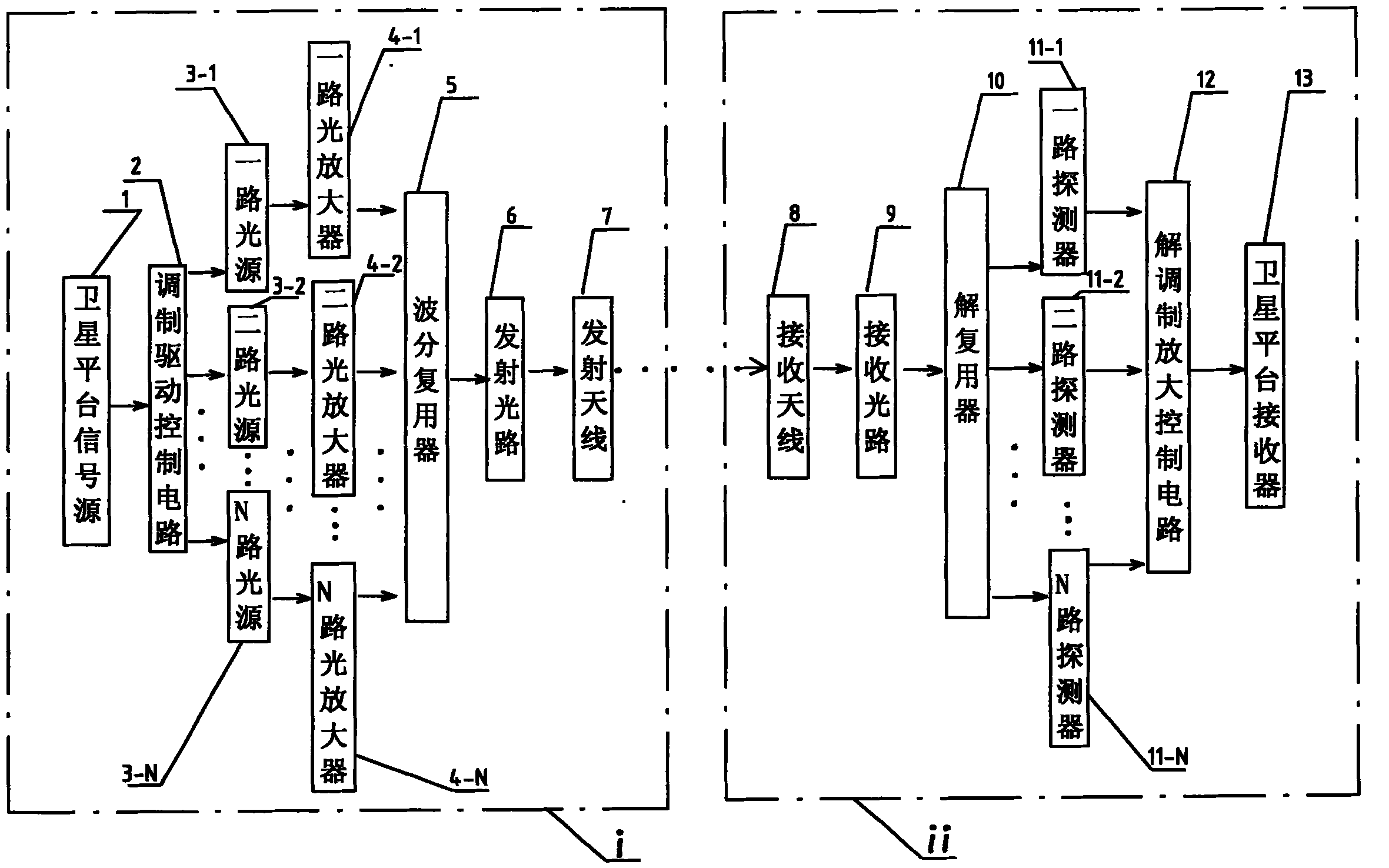
[0020] Specific Embodiment 1: The present embodiment will be specifically described below with reference to FIG. 1 . This embodiment is composed of a signal transmitting device i and a signal receiving device ii, and the signal transmitting device i consists of

[0021] Satellite platform signal source 1 that completes communication data encoding;

[0022] Receive the communication signal output by the satellite platform signal source 1, modulate the communication signal into N signal groups and output the modulation drive control circuit 2, and the N signal groups occupy adjacent bands;

[0023] Input a group of signals in N signal groups respectively, and convert the group of signals into laser signals output from one light source 3-1 to N light source 3-N, and output from one light source 3-1 to N light source 3-N The laser signal is within the wavelength range of 1270 to 1610nm, and the center wavelength of each two adjacent groups of laser signals is 20nm apart;

[0024...

specific Embodiment approach 2

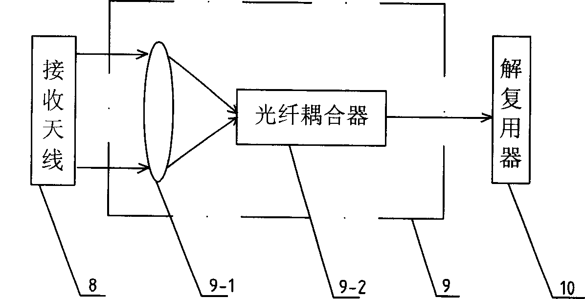
[0035] Specific embodiment two: below in conjunction with Fig. 1 and figure 2 This embodiment will be specifically described. The difference between this embodiment and Embodiment 1 is: the transmitting optical path 6 is a fiber collimator, the transmitting antenna 7 is a transmitting telescope, the receiving antenna 8 is a receiving telescope, and the receiving optical path 9 is composed of a focusing lens 9-1 and a fiber coupler 9- 2 components, the input end of the focusing lens 9-1 is connected to the output end of the receiving antenna 8, the input end of the fiber coupler 9-2 is connected to the output end of the focusing lens 9-1, and the output end of the fiber coupler 9-2 is connected to the demultiplexer The input terminal of the device 10. Choose one light source 3-1 to four light sources 3-4 in total, one amplifier 4-1 to four amplifiers 4-4 in total, one detector 11-1 to four detectors 11-4 in total four .

[0036] In the signal transmitting device i: one light...


PUM


Abstract

The invention consists of a signal radiating device and a signal receiving device. The radiating device comprises: satellite platform signal source for use in modulating the communication signal to the modulation drive control circuit of N signal groups and separately inputting one group of N signal groups, which is converted into one way to N way light source outputted from the laser signal output end; one way to N way amplifier used to make power amplification; wavelength division multiplexer used to synthesize beam; emitting light path; transmitting antenna. The signal receiving device comprises: receiving antenna, receiving optical path, demodulator for use in receiving the laser beam and separating it into N groups of laser signal, one way to N way detector for use in converting the laser signal into electrical signal, amplification control circuit for use in demodulating and amplifying N groups of electrical signal, and satellite platform receiver.

Description

technical field [0001] The invention relates to a communication system between a relay satellite and a low-orbit satellite. Background technique [0002] Compared with traditional microwave communication systems, inter-satellite optical communication has many advantages, including high data rate transmission capability, low-power terminal device composition, and safe and anti-jamming communication capability. The United States, Europe, Japan, Russia and China have successively carried out research on satellite optical communication technology. Due to the limitation of the development of semiconductor laser devices and the key technology of aiming, capturing and tracking, the optical communication terminals that have completed space experiments in foreign countries mostly use short wavelengths. For example, the optical communication between the relay satellite Artemis and the low-orbit satellite SPOT4 carried out by the European Space Agency in 2001, the laser wavelength is ...

Claims


Application Information

Patent Timeline
Patent Type & Authority Patents(China)
IPC IPC(8): H04J14/02H04L5/02
Inventor 谭立英马晶于思源韩琦琦
Owner HARBIN INST OF TECH
Why Eureka
Try Eureka