Circulation fluidized bed swirl-direct flow composite fluidizing device

A circulating fluidized bed and chemical device technology, applied in chemical instruments and methods, chemical/physical processes, separation methods, etc., can solve problems such as high internal circulation ratio, long residence time, airflow deflection, etc.

Inactive Publication Date: 2006-08-23
SHANDONG UNIV
View PDF1 Cites 10 Cited by
  • Summary
  • Abstract
  • Description
  • Claims
  • Application Information

AI Technical Summary

Problems solved by technology

Usually, the flue gas is introduced into the vertical channel of the desulfurization tower from one side of the desulfurization tower through the horizontal flue, which will cause the deflection of the airflow, affect its uniformity in the desulfurization tower, and cause the sticky wall on the side of the desulfurization flow. The traditional circulation Even if the fluidized bed uses guide vanes, it is difficult to av

Method used


Image

  • Circulation fluidized bed swirl-direct flow composite fluidizing device
  • Circulation fluidized bed swirl-direct flow composite fluidizing device
  • Circulation fluidized bed swirl-direct flow composite fluidizing device

Examples


Embodiment 1

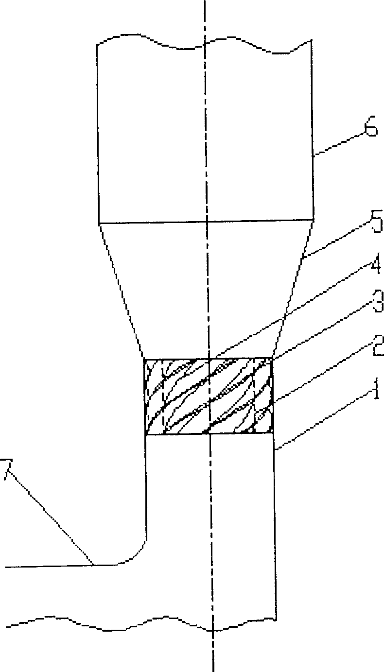
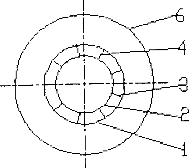
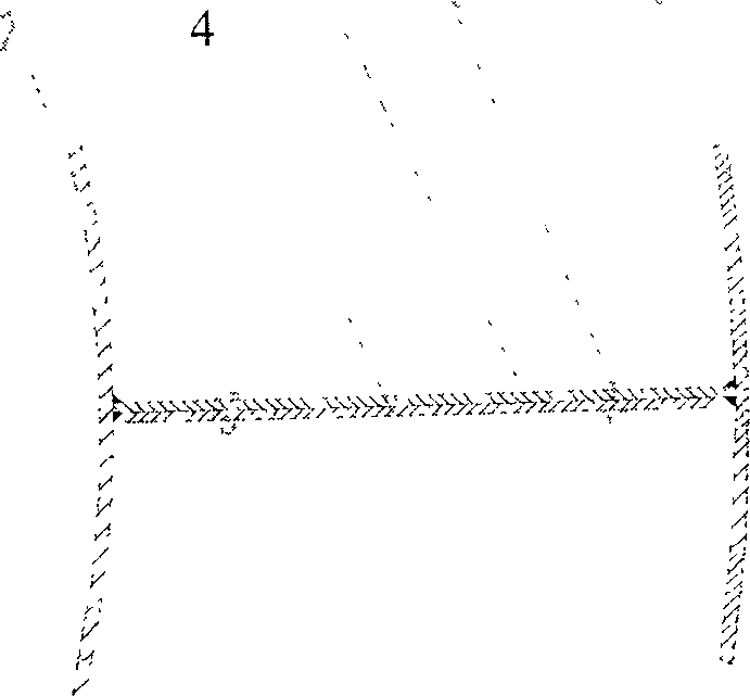
[0016] Example 1: For medium- or low-temperature circulating fluidized bed semi-dry flue gas desulfurization, the flue gas flows in horizontally through the inlet flue 7, rotates 90 degrees and then flows vertically upward through the venturi tube throat 1 and gradual expansion Section 5, enters the desulfurization tower. The inner sleeve 2 is installed in the Venturi tube throat 1, which is coaxial with the Venturi tube throat 1, and has a circular cross-section, whose cross-sectional area accounts for 60% of the Venturi tube throat 1, and the wall surface and the Venturi tube throat The walls of 1 are parallel, and the flue gas flowing in it is DC fluidization; between the inner sleeve 2 and the Venturi throat 1 is the swirl fluidization device 3, and the cross-sectional area of ​​the swirl fluidization device 3 occupies the venturi throat 40% of the cross-sectional area of ​​the pipe 1, the swirl fluidization device 3 is composed of 9 rotating blades 4, and the swirl fluidi...

Embodiment 2

[0017] Embodiment 2: The lower end of the inner sleeve 2 is located in the Venturi tube throat 1, and the upper end is located at half the height of the Venturi tube expansion section 5, and the cross-sectional area accounts for 70% of the cross-sectional area of ​​the Venturi tube expansion section 5 at the same height. , the wall surface of the inner sleeve 2 is parallel to the wall surface of the Venturi expanding section 5 and the Venturi tube throat 1 . The swirling fluidization device 3 is located between the expanding section 5 of the Venturi tube and the inner sleeve, the upper end of the swirling fluidizing device 3 is flush with the upper end of the inner sleeve 2, and the cross-sectional area of ​​the upper end occupies the same height as the venturi tube expanding 30% of the cross-sectional area of ​​the section 5, the height of the swirling fluidization device 3 is 30% of the height of the expanding section 5 of the Venturi tube, and there are 6 rotating blades 4 w...

Embodiment 3

[0018] Embodiment 3: The lower end of the inner sleeve 2 is located in the Venturi throat 1, and the upper end is located in the lower part of the desulfurization tower cylinder 6, and the cross-sectional area of ​​the inner sleeve 2 in the desulfurization tower cylinder 6 accounts for 10% of the desulfurization tower cylinder 6. 30% of the cross-sectional area, the wall surface of the inner sleeve 2 is parallel to the wall surfaces of the desulfurization tower body 6, the Venturi tube gradual expansion section 5, and the Venturi tube throat 1 respectively. The swirl fluidization device 3 is located between the desulfurization tower body 6 and the inner sleeve 2 , the upper end is flush with the upper end of the inner sleeve 2 , and the lower end is located at the inlet of the desulfurization tower body 6 . The cross-sectional area of ​​the swirl fluidization device 3 accounts for 70% of the cross-sectional area of ​​the desulfurization tower cylinder 6, and there are 15 rotati...


PUM


Abstract

The present invention belongs to the field of industrial waste gas purifying technology, and is one circular composite swirl-uniflow fluidizing device for fume desulfurizing fluidized bed. The fluidizing device includes an inlet fume channel, a Venturi tube, a reducing section and a desulfurizing barrel connected successively from bottom to top, and features that it includes also an inner sleeve installed inside the Venturi tube and a swirl fluidizing unit installed between the inner sleeve and the Venturi tube. Partial fume flows inside the inner sleeve and the rest flows in the swirl fluidizing unit, so as to form the composite fume fluidizing comprising the uniflow fluidizing inside the inner sleeve and swirl fluidizing outside the inner sleeve. The composite fluidizing device has simple structure, less gas flow deflection, high fluidizing effect, long grain retaining period, great inner circulation multiple and high desulfurizing efficiency.

Description

technical field [0001] The invention belongs to the fields of industrial waste gas purification, environmental protection and chemical industry, and in particular relates to a circulating fluidized bed swirling and direct current composite fluidization device for flue gas desulfurization. Background technique [0002] Currently used in flue gas desulfurization devices, a circulating fluidized bed fluidized by a Venturi tube is commonly used. The Venturi tube includes a Venturi tube throat and a diverging section. This kind of circulating fluidized bed has small resistance loss and large flue gas treatment capacity, but the disadvantage is that there is only one stream of flue gas in the center as a fluidized straight jet. For example, "a circulating suspension bed dry flue gas desulfurization process and its system" disclosed in the Chinese patent application number 00128285.9. structure. Usually, the flue gas is introduced into the vertical channel of the desulfurization ...

Claims


Application Information

Patent Timeline
IPC IPC(8): B01J8/24B01D53/83
Inventor 马春元郝晓文董勇徐夕仁王文龙张立强王春冰
Owner SHANDONG UNIV
Why Eureka
Try Eureka