Underground reciprocating oil puming machine driven by rotary motor

A rotating motor and reciprocating technology, which is applied in the direction of mining fluid, wellbore/well components, earthwork drilling and production, etc., can solve the problems of increased size, large inertial load, high energy consumption, etc., and achieve improved performance, small inertia, and flexibility Good results

Inactive Publication Date: 2006-08-23
HARBIN INST OF TECH
View PDF0 Cites 12 Cited by
  • Summary
  • Abstract
  • Description
  • Claims
  • Application Information

AI Technical Summary

Problems solved by technology

[0024] Aiming at the problems of high energy consumption, large horse-drawn carts, increased size after stroke increase and excessive inertial load in the existing pumping units, the prese

Method used


Image

  • Underground reciprocating oil puming machine driven by rotary motor
  • Underground reciprocating oil puming machine driven by rotary motor

Examples


specific Embodiment approach 1

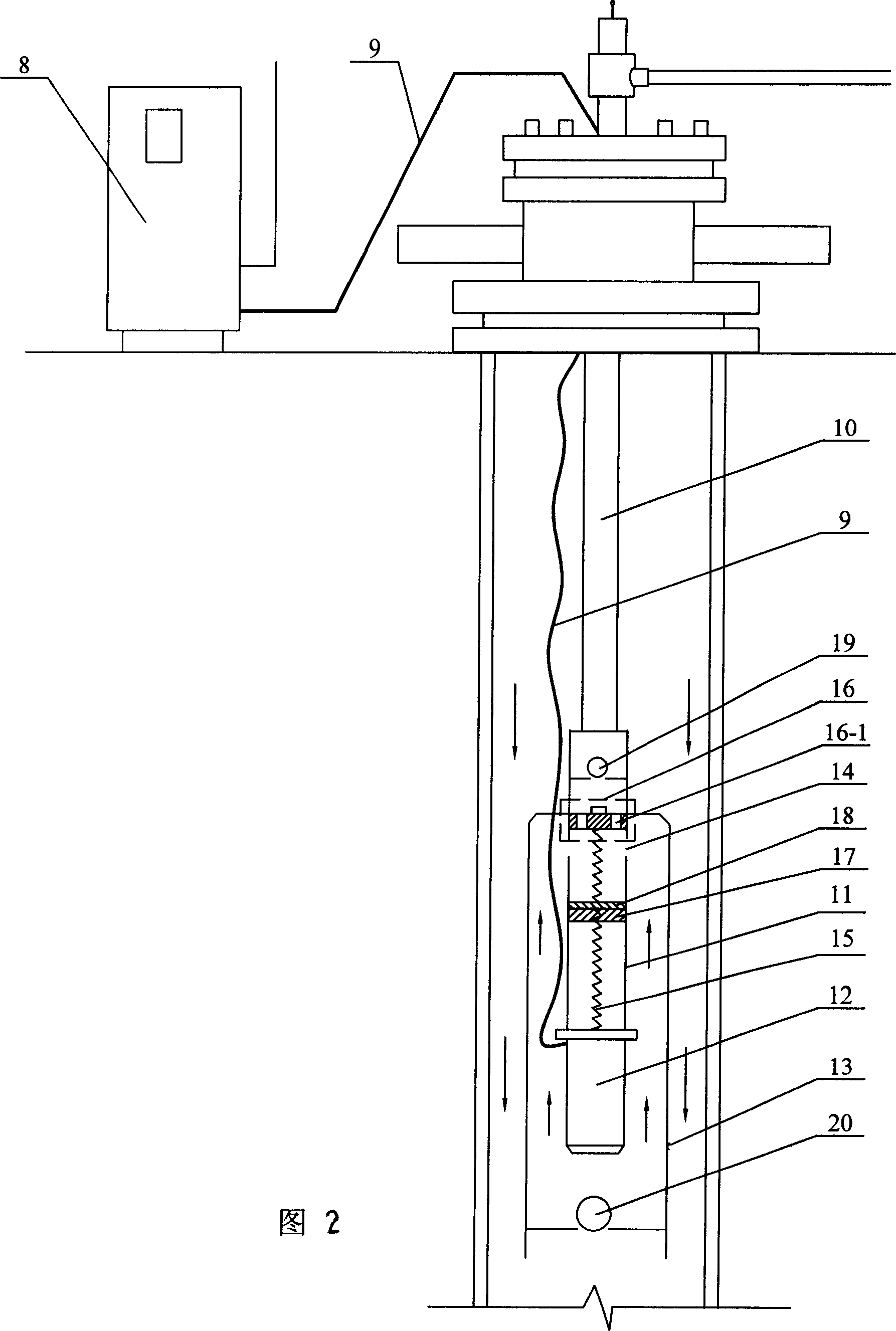
[0034] Embodiment 1: This embodiment is an underground reciprocating pumping unit driven by a rotating motor, which includes a motor controller 8, a cable 9, an oil outlet pipe 10, a plunger barrel 11, a motor 12, and a buffer oil pipe 13. The lower end of the oil outlet pipe 10 is sealingly connected with the plunger barrel 11, and the lower end of the plunger barrel 11 is provided with a motor 12, and a buffer oil pipe 13 is set outside the motor 12, and the upper end of the buffer oil pipe 13 is sealed with the outer wall of the plunger barrel 11 To connect, an oil suction hole 14 is provided on the inside of the buffer oil pipe 13 and on the side wall of the plunger barrel 11 , and a one-way oil inlet valve 20 is arranged in the buffer oil pipe 13 below the motor 12 . Both ends of the cable 9 are respectively connected with the motor controller 8 and the motor 12;

[0035] A lead screw 15 is arranged inside the plunger barrel 11, and the lower end of the lead screw 15 is c...


PUM


Abstract

The present invention relates to underground reciprocating oil pumping machine driven with a rotary motor, and relates to oil pumping machine. The underground reciprocating oil pumping machine has buffering oil pipe, motor set inside the buffering oil pipe, and motor output shaft connected to a lead screw. The motor rotates the lead screw to make the plunger fitting the lead screw move linearly, so as to convey raw oil from underground to surface. By means of transmission mode of rotating motor plus ball lead screw, the rotation of the motor is converted into the liner motion of the plunger pump. The present invention has the features of simple structure, smooth running, high system efficiency, good energy saving effect, capacity of meeting the requirement of automatic control and harsh condition of oil production, low cost, high reliability, etc.

Description

technical field [0001] The invention relates to an oil pumping unit. Background technique [0002] The most widely used conventional beam pumping unit oil recovery system is mainly composed of three parts: ground part: it consists of motor 1, reduction box 2 and four-bar linkage mechanism 3 (including crank, connecting rod, beam, beam), Composed of donkey head and rope hanger; underground part: oil pump 7, which is suspended at the lower end of oil pipe 5 in casing 6; the middle part connecting the ground and underground part: sucker rod column 4, which is composed of one or more Diameter sucker rods and couplings. The composition of conventional beam pumping unit oil production system is as follows: figure 1 shown. [0003] The pumping unit oil recovery system transfers electrical energy from the surface to the downhole fluid, thereby lifting the downhole fluid to the surface. The working process of the whole system is a process of continuous energy transfer and convers...

Claims


Application Information

Patent Timeline
IPC IPC(8): E21B43/00
Inventor 寇宝泉白相林李立毅
Owner HARBIN INST OF TECH
Why Eureka
Try Eureka