Full-compatible 3-D TV system realized by single lens two-light path camera

A technology of stereoscopic TV and camera, applied in the field of stereoscopic TV system, can solve the problems such as impossible real-time transmission of stereoscopic information on the news scene, poor stereoscopic TV effect, and difficulty in two-way compatibility of the system, so as to achieve less redundancy of source information. , the effect of strong stereoscopic effect and easy transmission

Inactive Publication Date: 2006-08-30
张德忠 +1
View PDF1 Cites 2 Cited by
  • Summary
  • Abstract
  • Description
  • Claims
  • Application Information

AI Technical Summary

Problems solved by technology

This type of system has the characteristics of real scenes and strong stereoscopic effect, because it is a direct simulation of human eyes, and it can also artificially increase the distance between cameras to enhance stereoscopic vision, but due to the relative independence of the optical system of the two cameras, this type of system It is difficult for the system to achieve two-way compatibility with existing TV standards, and at the same time, the system cost is high. At present, there is no stereoscopic TV system that uses this method to achieve two-way compatibility.
[0005] The second type is to utilize the feature that one eye of a person can also obtain a stereoscopic impression, and two images of a pair of parallax signals appear on the screen in turn, thereby obtaining stereoscopic vision; this type of stereoscopic TV is easy to realize and existing TV Standard compatible, but according to the stereoscopic vision mechanism of the human eye, in order to obtain stereoscopic vision with a single camera, a specific shooting method must be used, such as allowing the camera to rotate around a fixed focus continuously. Patent No. 98101085.7 invented a fully compatible and flicker-free The time-division stereoscopic TV system is realized in this way, but the system puts forward high technical requirements for the camera technicians, there is no stereoscopic vision when the camera is still, and it is impossible to realize the stereoscopic information for the news scene with uncertain focus of the scene. real-time delivery
Among them, the three-dimensional TV system based on the Sanger principle is the most distinctive. It places a complementary coded color filter with red on the left and green on the right at the lens aperture of the camera. When the camera shoots a scene with depth, the scene on the focus plane A clear and good normal-color image point is formed on the target surface of the camera, and the vertical boundary line of the subject that is not on the focal plane will become a double linear color border of red and cyan. We use the red on the left and the cyan on the right The glasses that are complementary colors just can see the image that left and right eyes have chromatic parallax on the display screen, thus form stereoscopic vision; It has realized two-way compatible with existing television system well; But the stereoscopic television system of Sanger principle It is to convert the stereoscopic information into the color signal on the defocus point (accurately speaking, it is the color fringing of the vertical edge of the object not on the focal plane) for transmission. Everyone knows that the color signal is carried out whether it is the current ordinary TV system or the high-definition TV system. The lower-frequency color signal after bandwidth compression (that is, the principle of large-area coloring), and the TV stereo information (the information difference between the left-eye image and the right-eye image) is just the middle and high-frequency components of the image signal. The stereo signal will be filtered out in the chrominance channel, so it is difficult to use the existing TV system to completely transmit the colored stereo information, which will inevitably cause a large loss of stereo information, so the stereo TV effect achieved by using it Not good, poor three-dimensional sense
[0007] Up to now, there is no stereoscopic TV system that can truly realize two-way compatibility with existing TV standards and transmit stereoscopic images in real time.

Method used


Image

  • Full-compatible 3-D TV system realized by single lens two-light path camera
  • Full-compatible 3-D TV system realized by single lens two-light path camera
  • Full-compatible 3-D TV system realized by single lens two-light path camera

Examples


Embodiment Construction

[0041] Embodiments of the present invention will be described in further detail below in conjunction with the accompanying drawings.

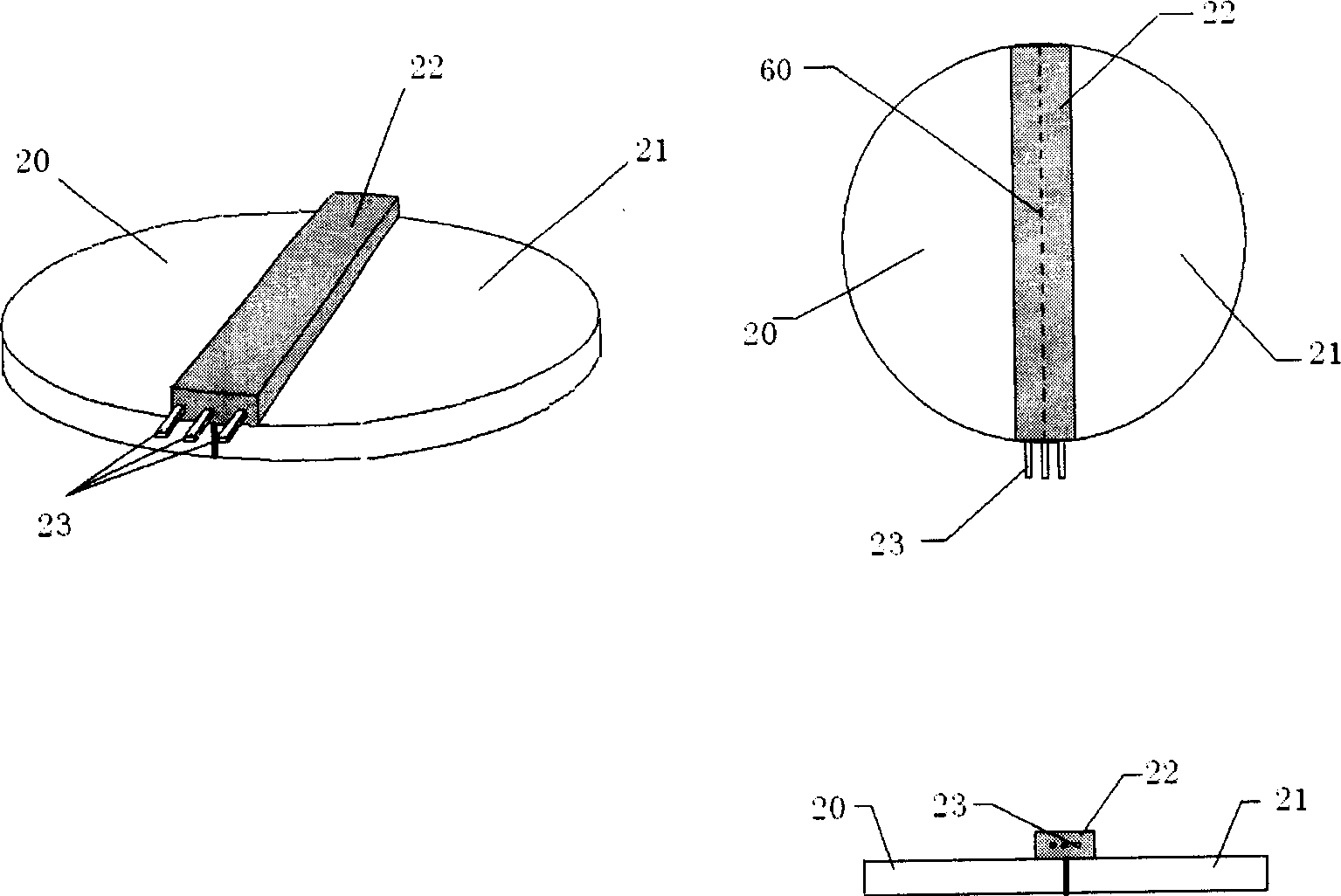
[0042] figure 2 It is a structural schematic diagram of the left and right anti-phase optical switches to be added to the stereo camera of the present invention. It is composed of two symmetrical optical switches on the left and right; 20 is the left optical switch; 21 is the right optical switch; The longitudinal central axis of the switch is the left and right symmetrical central axis of each part on the light-passing working surface of the optical switch, and is the longitudinal dividing line of the optical path of the camera; Affects the stereoscopic imaging, but it is necessary to ensure that the divisions are longitudinally symmetrical on the central axis 60 of the optical switch, and ensure that the luminous flux of the entire optical path meets the system performance requirements. The diameter of the optical switch should be greater ...


PUM


Abstract

This invention puts forward a total compatible stereoscopic TV system realized by a mono-lens double optical path camera characterizing that an optical switch of right and left inversion is placed at the position of a focus object lens of a camera to separate the parallax images of right and left eyes controlled by the field synchronization and the parallax image signals are processed and added by stereo-synchronous signals and transmitted to a TV receiver via an ordinary TV system, the receiver displays the panel image again without double images and containing stereo-information watched by bared eyes, an optical polarizer controlled by stereo-synchronous signals assigns the mutual-vertical optical polarization character to adjacent field TV pictures and uses related polarized glass to watch 3-D relief TV images.

Description

technical field [0001] The invention belongs to a stereoscopic television system with binocular stereoscopic vision characteristics that realizes two-way compatibility with existing flat-screen televisions, naked-eye viewing without ghosting, and shooting with a single camera. Background technique [0002] Before the 3D TV system standard was released, various 3D TV system designs competed with each other. Analyzing the principles of various stereoscopic TV systems, most of them have worked hard to solve the problems of stereoscopic strength and compatibility. [0003] According to the two visual characteristics of binocular stereo vision and monocular stereo vision of the human eye, there are two main types of ways to realize stereo TV: [0004] One is to use the parallax characteristics of the eyes to make two images of a pair of parallax signals appear on the screen at the same time, and let the two eyes watch the two images separately to obtain stereoscopic vision. Thi...

Claims


Application Information

Patent Timeline
Patent Type & Authority Applications(China)
IPC IPC(8): H04N13/00H04N15/00
Inventor 张德忠
Owner 张德忠
Why Eureka
Try Eureka