Arc welding control device

A technology of arc welding and control unit, which is applied in arc welding equipment, devices for supplying/removing shielding gas, manufacturing tools, etc. It can solve the problems of time spent on maintaining equipment, achieve the effect of improving maintenance and ensuring reliability

Inactive Publication Date: 2006-08-30
PANASONIC CORP
View PDF1 Cites 14 Cited by
  • Summary
  • Abstract
  • Description
  • Claims
  • Application Information

AI Technical Summary

Problems solved by technology

[0008] However, in the conventional arc welding control unit, since the air outside the equipment is applied to the entire main semiconductor and thus cools it, a probl

Method used


Image

  • Arc welding control device
  • Arc welding control device
  • Arc welding control device

Examples


Embodiment approach 1

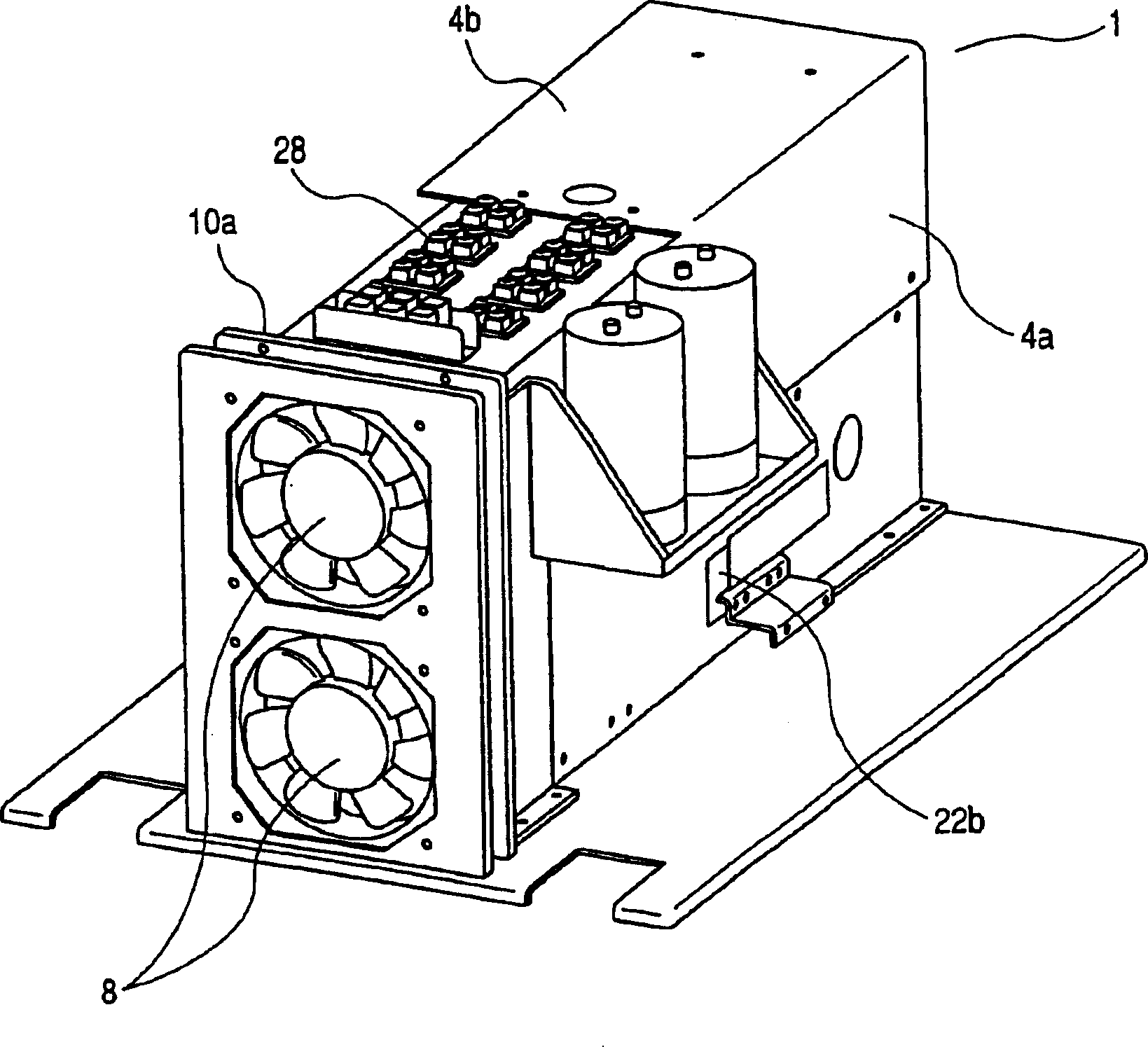
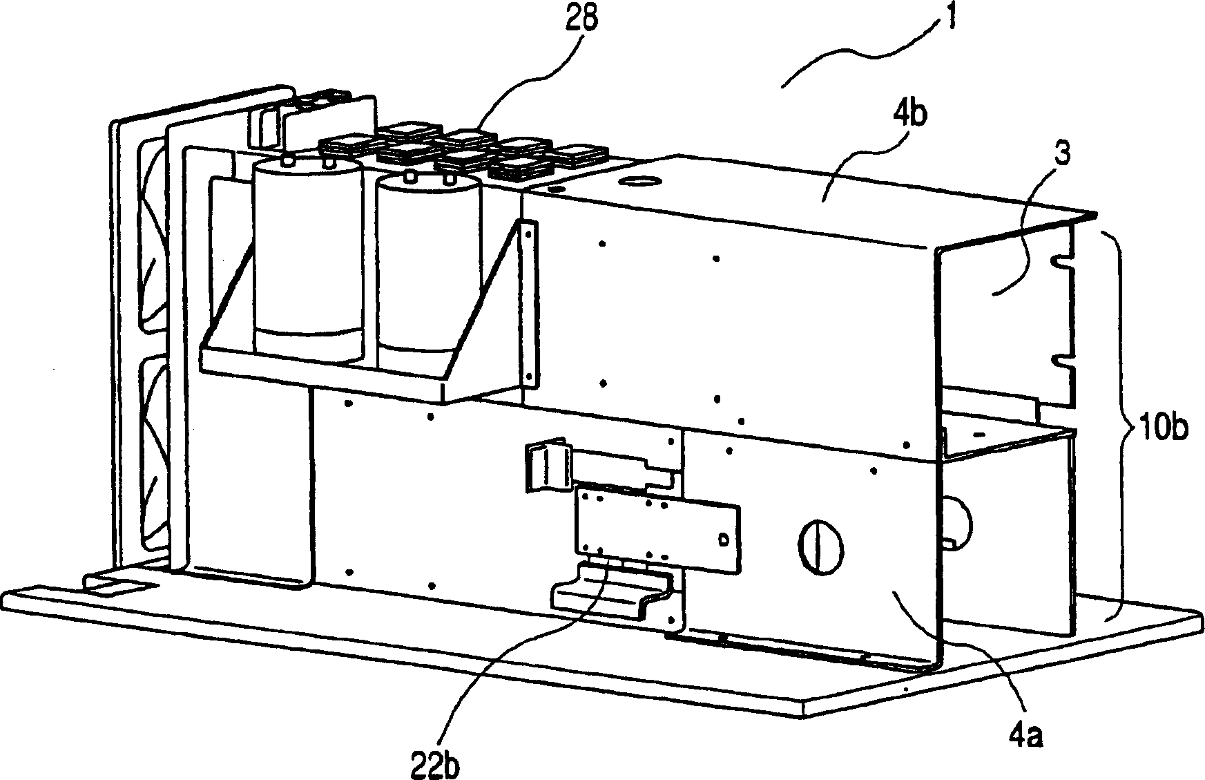
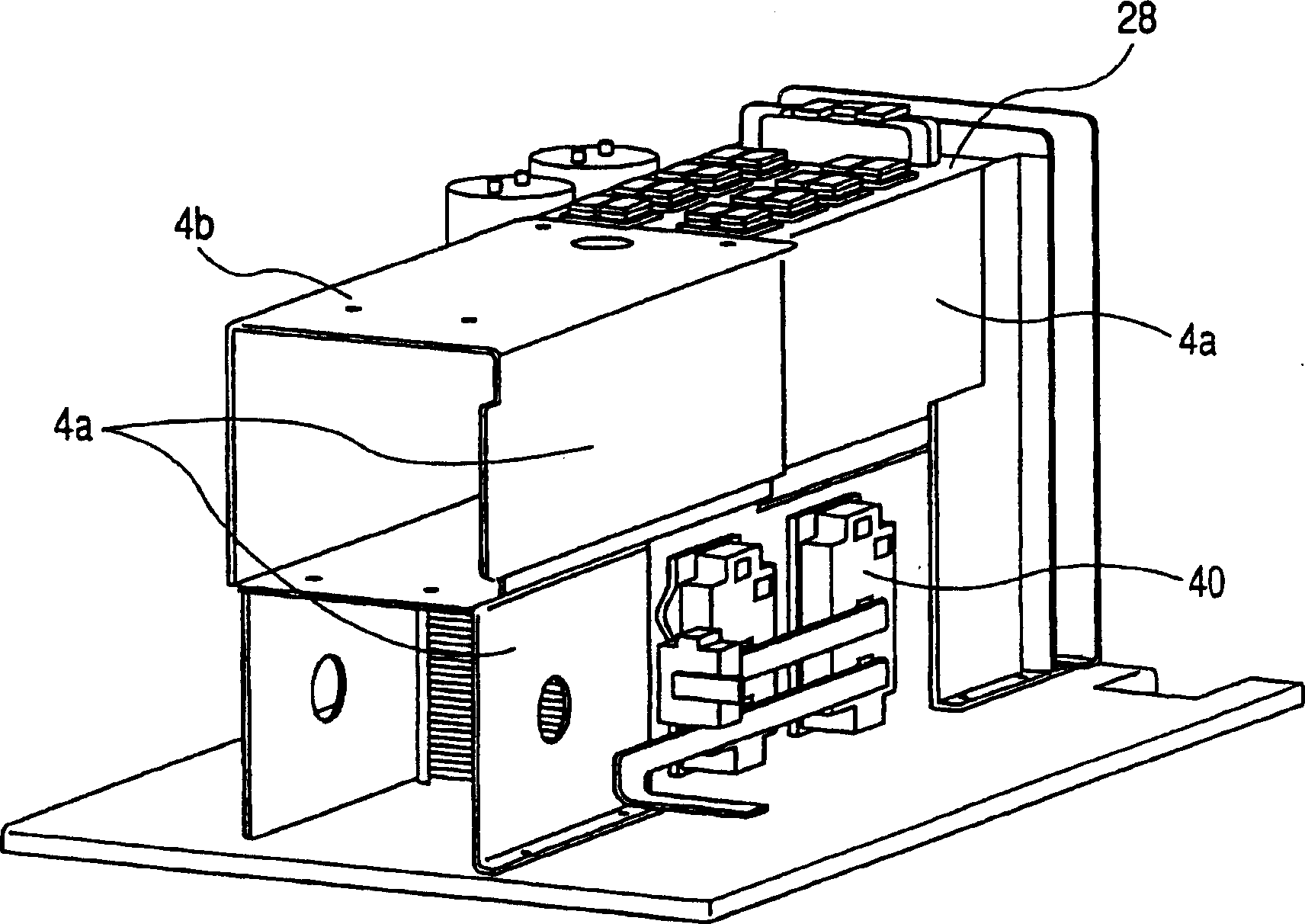
[0016] First, refer to Figure 5 , to briefly describe the circuit structure of the arc welding control unit according to this embodiment of the present invention. Figure 5 is a circuit diagram of the circuit configuration of the arc welding control unit according to this embodiment. Figure 5 , a portion shown by a single-dot chain line and denoted by reference numeral 20 is a primary side inverter circuit (inverter circuit), 28 denotes a power transistor used as an inverter (switching device) in the primary side inverter circuit 20, 21 Denotes a main transformer, a portion shown by a two-dot chain line and denoted by reference numeral 22 is a secondary side main circuit, 23 denotes a DC reactor, and 34 denotes a control circuit.

[0017] Next, the operation of this embodiment will be briefly described with reference to the above-described circuit configuration. The electric power supplied from the commercial power source 25 is rectified by the primary rectifying diode 26 ...


PUM


Abstract

Cooling by directly blowing air outside an apparatus toward the entire main circuit has deposited or attached dust, weld fumes or the like to conductive units inside the apparatus, thus requiring a substantial time for maintaining the apparatus. An arc welding control device having a radiation unit that exhausts to the outside air heated by a heating electric element and is built in a casing, wherein the radiation unit has a tunnel shape provided with an outer peripheral portion forming a hollow portion to let air flow therethrough, thereby making it possible to prevent depositing or attaching of dust, weld fumes or the like to the conductive units inside the apparatus.

Description

technical field [0001] The invention relates to an arc welding control unit. Background technique [0002] Recently, the operating speed of industrial equipment has been greatly increased. Under such circumstances, attention has been paid to the convenience of maintenance of the arc welding control unit. [0003] Figure 8 is a perspective view of a conventional arc welding control unit, specifically, a perspective view of a case portion provided outside the control unit. exist Figure 8 Among them, reference numeral 101 denotes a box for an arc welding control unit, 102 denotes an air inlet / outlet, 103 denotes a fan, 104 denotes a radiator, and 105 denotes a main semiconductor. Incidentally, actually, there are also various components and wires for performing arc welding; however, since they have no direct relation to the description of the present invention, their descriptions are omitted. In addition, the description of the circuit configuration of the control unit is ...

Claims


Application Information

Patent Timeline
IPC IPC(8): B23K9/32B23K9/073H02M9/00H05K7/20
CPCB23K9/325H05K7/20909
Inventor 大山英俊田畑芳行武藤泰道向井康士
Owner PANASONIC CORP
Why Eureka
Try Eureka