Waste gas treatment device

A technology of waste gas treatment device and spray device, which is applied in the direction of dispersed particle separation, chemical instruments and methods, and the use of liquid separating agent, etc., which can solve problems such as effect to be improved and structural limitations

Inactive Publication Date: 2006-09-13
绍兴永利环保科技有限公司
View PDF0 Cites 26 Cited by
  • Summary
  • Abstract
  • Description
  • Claims
  • Application Information

AI Technical Summary

Problems solved by technology

The exhaust gas atomization absorption processor disclosed on October 26, 2005 with the publication number CN1686595A can effectively treat the exhaust gas of the setting machine and recycle the heat in the exhaust gas, but due to structural limitations, the effect is still to be determined. improved

Method used


Image

  • Waste gas treatment device
  • Waste gas treatment device
  • Waste gas treatment device

Examples


Embodiment Construction

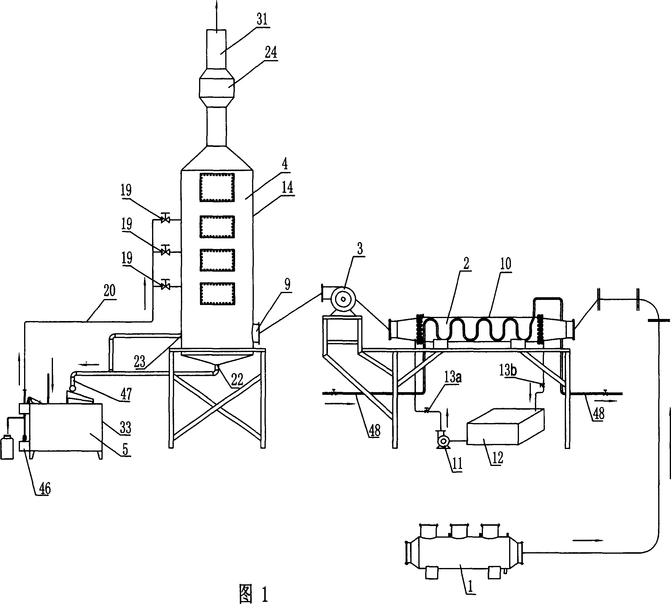
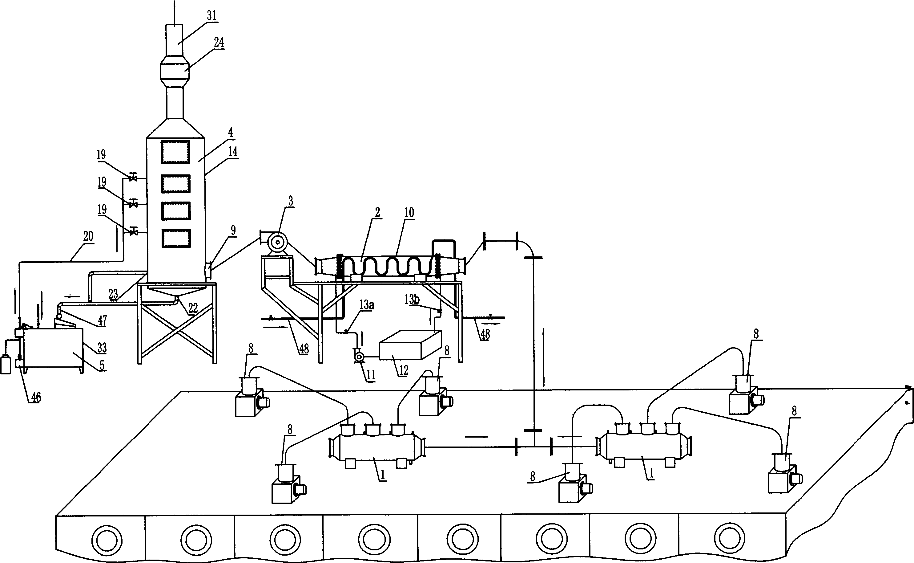
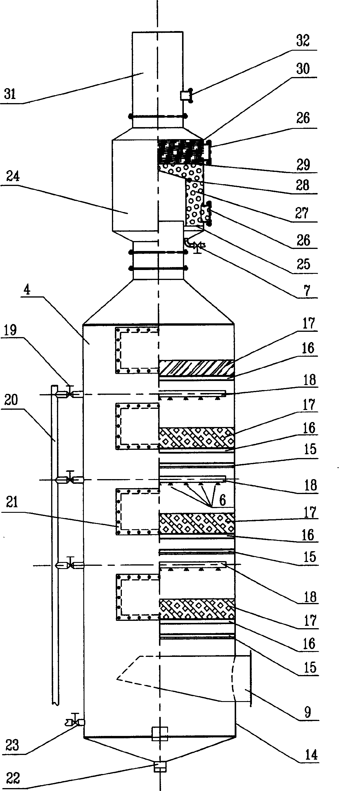
[0016] Figure 1, figure 2 As shown, the exhaust gas treatment device includes a flue gas concentrator 1, a heat exchanger 2, a spray packed tower 4, and an oil-water separator 5. One end of the heat exchanger 2 is connected to the flue gas concentrator 1 through a pipe, and the other end is connected to the flue gas concentrator 1 through a pipeline. The pipeline communicates with the air inlet 9 of the spray packed tower 4, and the oil-water separator 5 forms a circulation connection with the spray packed tower 4. image 3 Shown spray packing tower 4 comprises the tower body 14 that top is provided with mist eliminator 24, interior is provided with spraying device 18, and tower body 14 bottom and side are respectively provided with drain hole 22 and air inlet 9, tower An overflow hole 23 is also provided below the side wall of the body 14, and a water inlet distribution pipe 47 is connected between the drain hole 22 and the overflow hole 23, and the water outlet end of the wa...


PUM

PropertyMeasurementUnit
angleaaaaaaaaaa

Abstract

A waste gas treating apparatus for atomizing, dusting and absorbing the waste gas coming from the dyeing and finishing industry is composed of fume gathering unit, heat exchanger for recovering heat, sprinkling filler tower and oil-water separator for reclaiming them.

Description

technical field [0001] The invention discloses a waste gas treatment device, in particular to an atomization dust removal and absorption treatment for waste gas in a setting machine in the dyeing and finishing industry, and belongs to the technical field of environmental protection devices. Background technique [0002] my country is a big textile country and also the largest country in the world's printing and dyeing industry. The setting machine is the key equipment for textile printing and dyeing finishing. During the processing of the setting machine, a large amount of exhaust gas is discharged. The exhaust gas contains harmful components such as smoke, oil stains, and dye auxiliaries. At the same time, a large amount of waste heat is discharged into the air. The lost heat is not only a waste of energy, but also causes environmental pollution. It is necessary to effectively control the waste gas of the setting machine and recover the waste heat of the waste gas. The use of...

Claims


Application Information

Patent Timeline
Patent Type & Authority Applications(China)
IPC IPC(8): B01D47/14B01D53/78
CPCY02P70/10
Inventor 何雅花王根武朱衍洲刘嵩
Owner 绍兴永利环保科技有限公司
Why Eureka
Try Eureka