
Loading table and heat treating apparatus having the loading table

A technology of heat treatment device and placement table, applied in lighting and heating equipment, gaseous chemical plating, furnace components, etc., can solve the problem of shortening cleaning treatment and maintenance interval, uneven temperature of wafer surface, and reducing in-plane uniformity of wafer heat treatment And other issues

Inactive Publication Date: 2006-09-13
TOKYO ELECTRON LTD
View PDF4 Cites 7 Cited by
  • Summary
  • Abstract
  • Description
  • Claims
  • Application Information

AI Technical Summary

Problems solved by technology

In this case, since the heat emissivity is different on the thicker part and the thinner part of the attached unnecessary film, so, with it as a reason, the surface temperature of the mounting table is distributed, so that the wafer surface is caused Temperature unevenness, which reduces the in-plane uniformity of the heat treatment of the wafer
[0009] In addition, since the unnecessary film attached to the surface of the table or the surface of the cover is easy to peel off quickly, it is necessary to perform cleaning treatment before the unnecessary film peels off to shorten the maintenance interval of cleaning treatment and the like. , therefore, frequent maintenance operations are necessary
In addition, in the case where heating can be performed for each area of ​​the placement table as a heating body, when the difference in power input to each area is large, due to the thermal expansion of the material of the heater, the placement table may be damaged. Damage and other issues

Method used


Image

  • Loading table and heat treating apparatus having the loading table
  • Loading table and heat treating apparatus having the loading table
  • Loading table and heat treating apparatus having the loading table

Examples


Embodiment Construction

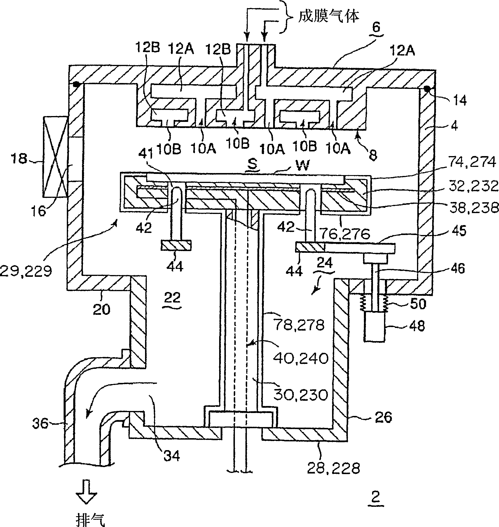
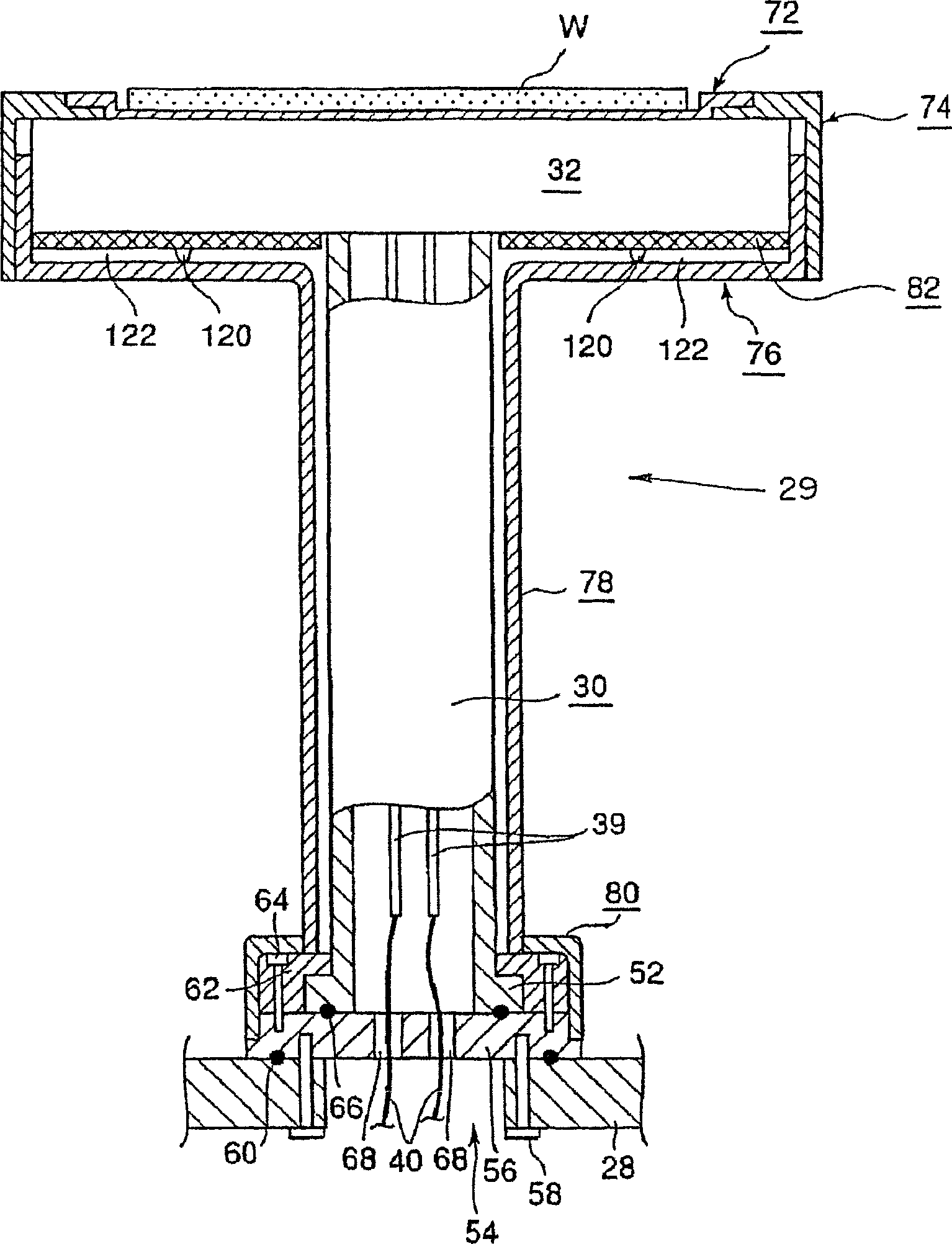
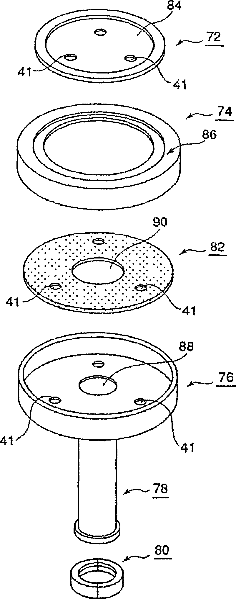
[0066] Below, according to Figure 1 to Figure 13 , the embodiment of the heat treatment apparatus having the placing table structure of the present invention will be described in detail.

[0067] Figure 1 ~ Figure 3 It is a schematic diagram which shows 1st Embodiment of this invention.

[0068] figure 1 It is a cross-sectional view showing a heat treatment apparatus having a placing table structure of the present invention, figure 2 is a cross-sectional view showing the structure of the mounting table, image 3 yes means figure 2 An exploded view of the lid part of the placement table structure shown.

[0069] As shown in the figure, the heat treatment apparatus 2 has, for example, an aluminum processing container 4 whose cross-section is substantially circular inside. The top of the processing container 4 is provided with a shower 6 as a gas supply device for introducing necessary processing gas (such as a film-forming gas), and the processing gas is sprayed from a...


PUM


Abstract

A heat treating apparatus, wherein a treated body (W) is placed on the upper surface of a loading table (32) which is erected from the bottom part of a treatment container (4) through a column and in which a heating means (38) is buried and a specified heat treatment is applied to the treated body. Insulating cover members (72), (74), and (76) are installed on the upper surface, side surface, and lower surface of the loading table. Thus, since metallic atoms causing contamination can be prevented from being thermo-diffused from the loading table, various contaminations such as metallic contamination and organic substance contamination can be prevented from occurring.

Description

technical field [0001] The present invention relates to a placing table structure for placing an object to be processed such as a semiconductor wafer, and a heat treatment apparatus having the placing table structure. Background technique [0002] Generally, in the manufacture of semiconductor integrated circuits, various single-chip processes such as film formation, etching, heat treatment, modification, and crystallization are repeatedly performed on a target object such as a semiconductor wafer to form a desired integrated circuit. . In the case of performing the above-mentioned various treatments, it is necessary to introduce necessary processing gases into the processing container according to the type of processing. It is necessary to introduce ozone gas, etc., and in the case of crystallization treatment, it is necessary to introduce N 2 Inert gas such as gas or O 2 gas etc. [0003] For example, taking a monolithic heat treatment apparatus that heats each of semi...

Claims


Application Information

Patent Timeline
IPC IPC(8): H01L21/205H01L21/31C23C16/44F27D3/12H01L21/22H01L21/324H01L21/68H01L21/683
Inventor 川崎裕雄岩田辉夫纲仓学
Owner TOKYO ELECTRON LTD
Learn More