Pulsation axial flow blood pump

A pulsating shaft and blood technology, applied in axial flow pumps, pumps, non-variable volume pumps, etc., can solve the problems of blood destruction of thrombus and wear, reduce the chance of thrombosis, improve service life, and reduce energy consumption. Effect

Inactive Publication Date: 2006-09-20
张杰民 +1
View PDF0 Cites 24 Cited by
  • Summary
  • Abstract
  • Description
  • Claims
  • Application Information

AI Technical Summary

Problems solved by technology

And the wear between the journal of the axial flow pump and its bearing will lead to the destruction of blood and the formation of thrombus

Method used


Image

  • Pulsation axial flow blood pump
  • Pulsation axial flow blood pump

Examples


Embodiment Construction

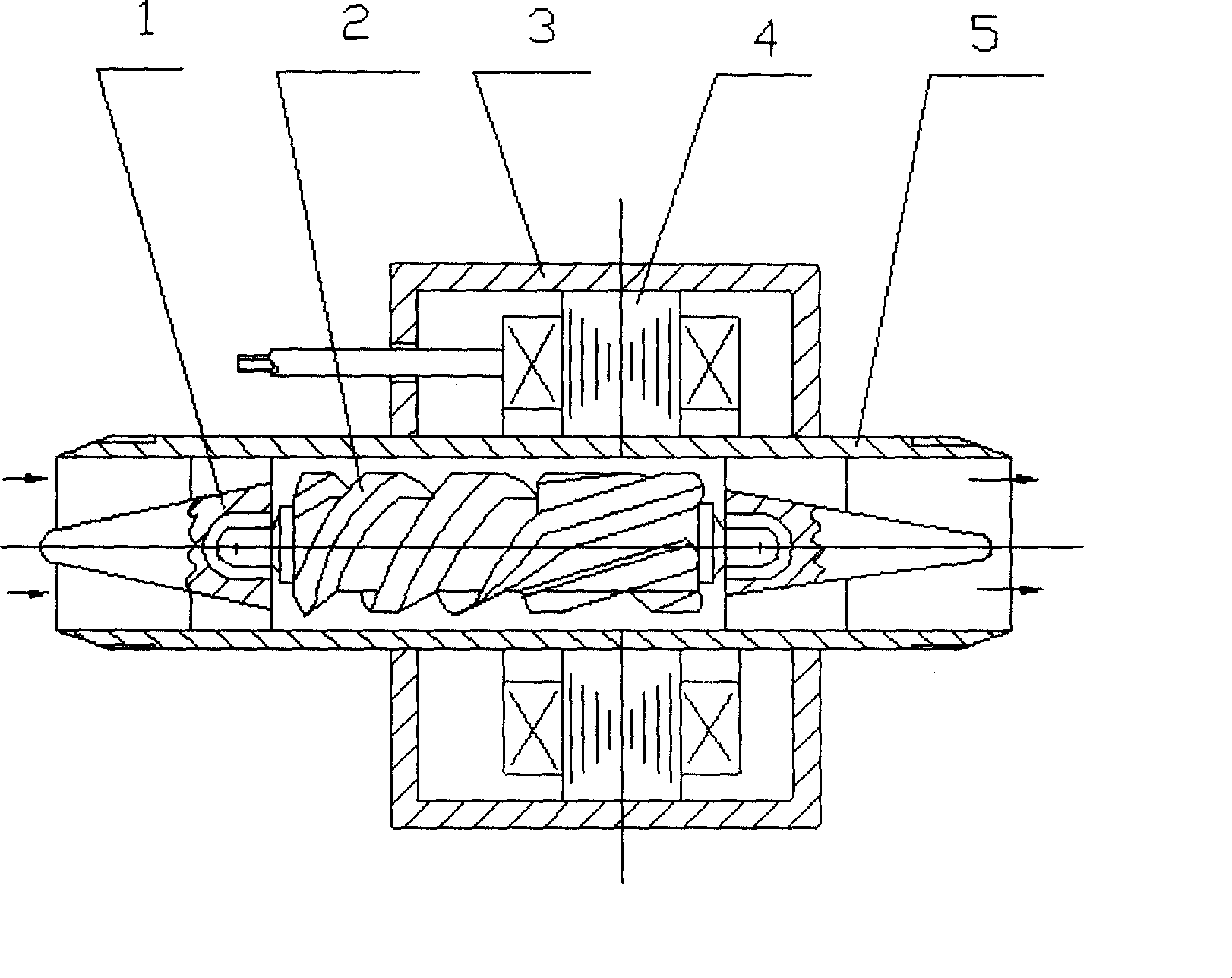
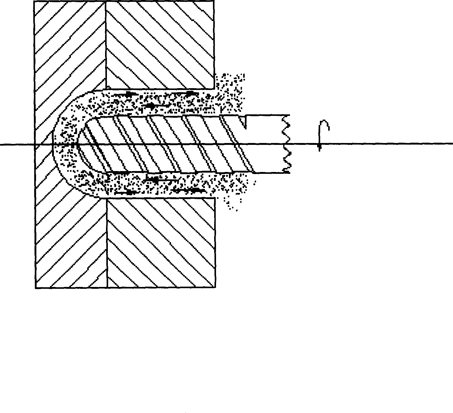
[0024] The pulsating axial flow blood pump of the present invention includes: (1) stator windings wound on the stator core; (2) a cylindrical rotor located in the center of the axial flow pump; (3) the rotor consists of multiple pairs of columnar magnets , located in the outflow path; (4) A number of helical blades are fixed on the surface of the rotor, located in the inflow path; (5) The rotor is placed into the supporting bushing through the two cylindrical shaft ends of the central shaft, and the shaft ends are made of dynamic pressure liquid floating technology. The rotor is suspended. (6) The stator winding is sealed in the casing with epoxy resin, and the casing is sealed by laser welding. (7) The circuit board of the DC brushless motor is controlled by computer software to realize the pulsating speed generated by the current, voltage, pulse width and frequency of the stator winding, and the permanent magnet rotor is driven to drive the helical propulsion device to rotat...


PUM


Abstract

An axial-flow pulse blood pump for the patient of acute heart failure and final-phase heart disease is composed of a stator consisting of windings and shell, and a rotor consisting of high-energy magnet and propulsion unit. Said propulsion unit comprises spiral rotor, central axle and three pairs of cylindrical magnets to form a sealed one-way spiral blood channel. The rotation speed of rotor is pulsed by changing the pulse width and frequency of voltage or current in stator.

Description

technical field [0001] The present invention relates to a pulsatile heart assist pump. Background technique [0002] During nearly half a century of research on cardiac assist devices, their materials, structures, manufacturing processes, functions, and service life have been continuously improved and developed, and different drive methods such as pneumatic, electric, and electro-hydraulic have emerged. The blood flow is also closer to the physiological heart. Cardiac assist devices are an important means of maintaining life in critically ill patients. It is divided into three ways: final replacement, waiting for transplantation, reducing cardiac load, and promoting functional recovery. [0003] According to statistics, there are 4 million heart failure patients in my country. With the continuous development of medical science, there are more and more patients with acute heart failure, unable to leave the extracorporeal circulation machine after cardiac surgery, waiting f...

Claims


Application Information

Patent Timeline
Patent Type & Authority Applications(China)
IPC IPC(8): A61M1/10F04D3/00
Inventor 张杰民薛恒春万峰
Owner 张杰民
Why Eureka
Try Eureka