Heat pipe, heat pipe multiporous structure and its mfg. method

A porous structure and heat pipe technology, applied in the field of heat pipes, can solve the problems of damaged heat pipes, dry burning, and inability to quickly replenish evaporated liquids, etc.

Inactive Publication Date: 2006-09-20
FU ZHUN PRECISION IND SHENZHEN +1
View PDF0 Cites 6 Cited by
  • Summary
  • Abstract
  • Description
  • Claims
  • Application Information

AI Technical Summary

Problems solved by technology

When the end of the heat pipe absorbing heat increases, the evaporation speeds up, and the speed of the liquid decreases due to the backflow resistance, which may cause the evaporated liquid at the heat-absorbing end to be unable to be quickly replenished, resulting in dry burning and damage to the heat pipe

Method used


Image

  • Heat pipe, heat pipe multiporous structure and its mfg. method
  • Heat pipe, heat pipe multiporous structure and its mfg. method
  • Heat pipe, heat pipe multiporous structure and its mfg. method

Examples


Embodiment Construction

[0020] Further description will be made below in conjunction with the embodiments with reference to the accompanying drawings.

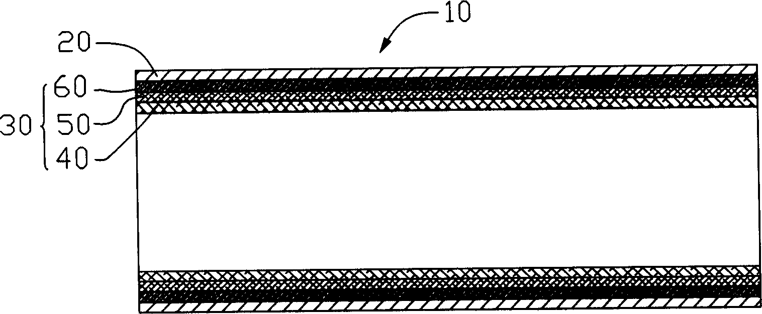
[0021] Such as figure 1 As shown, the heat pipe 10 includes a pipe body 20 , a porous structure 30 in close contact with the inner wall of the pipe body 20 and a working liquid filled in the pipe body 20 .

[0022] The tube body 20 is made of a metal material with good thermal conductivity, such as copper, etc. The cross section of the tube body 20 is circular, and the cross section of the tube body 20 can also be in other shapes, such as roughly oval, triangular, rectangular and other polygonal shapes. Wait. The working liquid filled in the pipe body 20 is generally a liquid with a low boiling point, such as water, alcohol and the like.

[0023] The porous structure 30 is composed of three layers of wire mesh with approximately equal thickness and in close contact with each other. The inner layer wire mesh 40 , the middle layer wire mesh 50 , and...


PUM


Abstract

The present invention relates to a heat pipe porous stracture, including silk screen which is made up by using silk yarn through a certain knitting process. Said porous structure has pores with different apertures, and said pore sizes are formed into gradient distribution along the radial direction or longitudinal direction of heat pipe. The manufacture method of said heat pipe porous structure includes the following steps: rolling the above-mentioned flake silk screen with different pores into cylindrical silk screen, then placing the cylindrical silk screen into pipe body of heat pipe.

Description

【Technical field】 [0001] The invention relates to heat pipes, in particular to a mesh-type porous structure, a manufacturing method thereof, and a heat pipe with a mesh-type porous structure. 【Background technique】 [0002] With the continuous advancement and wide application of large-scale integrated circuit technology, high-frequency and high-speed processors are continuously introduced. Due to the high-frequency and high-speed operation, the processor generates a large amount of heat per unit time. If the heat is not removed in time, the temperature of the processor itself will rise, which will have a great impact on the safety and performance of the system. At present, heat dissipation has become a new generation of high-speed processing. Issues that must be resolved when the device is rolled out. [0003] Due to the ever-increasing demand for heat dissipation, new types of heat sinks continue to emerge. The application of heat pipes to heat dissipation of electronic c...

Claims


Application Information

Patent Timeline
Patent Type & Authority Applications(China)
IPC IPC(8): F28D15/02G06F1/20
Inventor 洪居万吴荣源郑景太骆长定
Owner FU ZHUN PRECISION IND SHENZHEN
Why Eureka
Try Eureka