Electric network reactive compensator and method thereof
A compensation device and compensation method technology, applied in the direction of reactive power compensation, reactive power adjustment/elimination/compensation, etc., can solve the problems of compensation capacitor and other equipment damage, limiting compensation effect, switching oscillation, etc., to avoid overvoltage High hazard, significant economic benefits, and the effect of saving equipment investment
- Summary
- Abstract
- Description
- Claims
- Application Information
AI Technical Summary
Problems solved by technology
Method used
Image

Examples
Embodiment 1
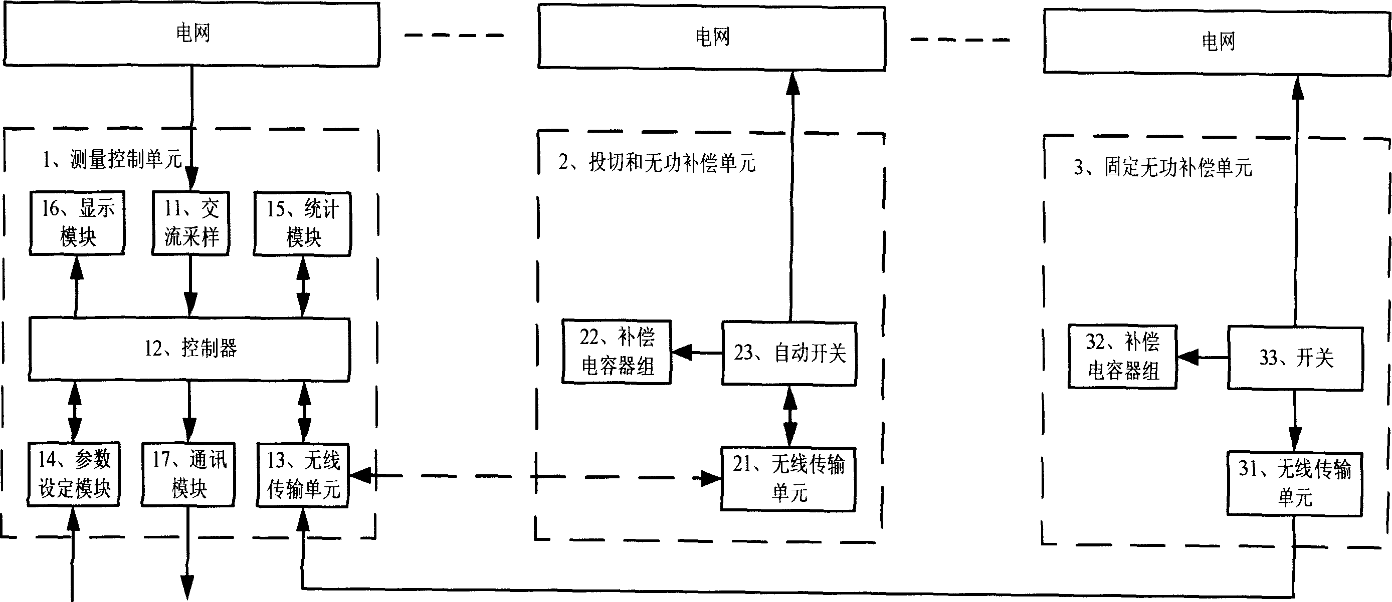
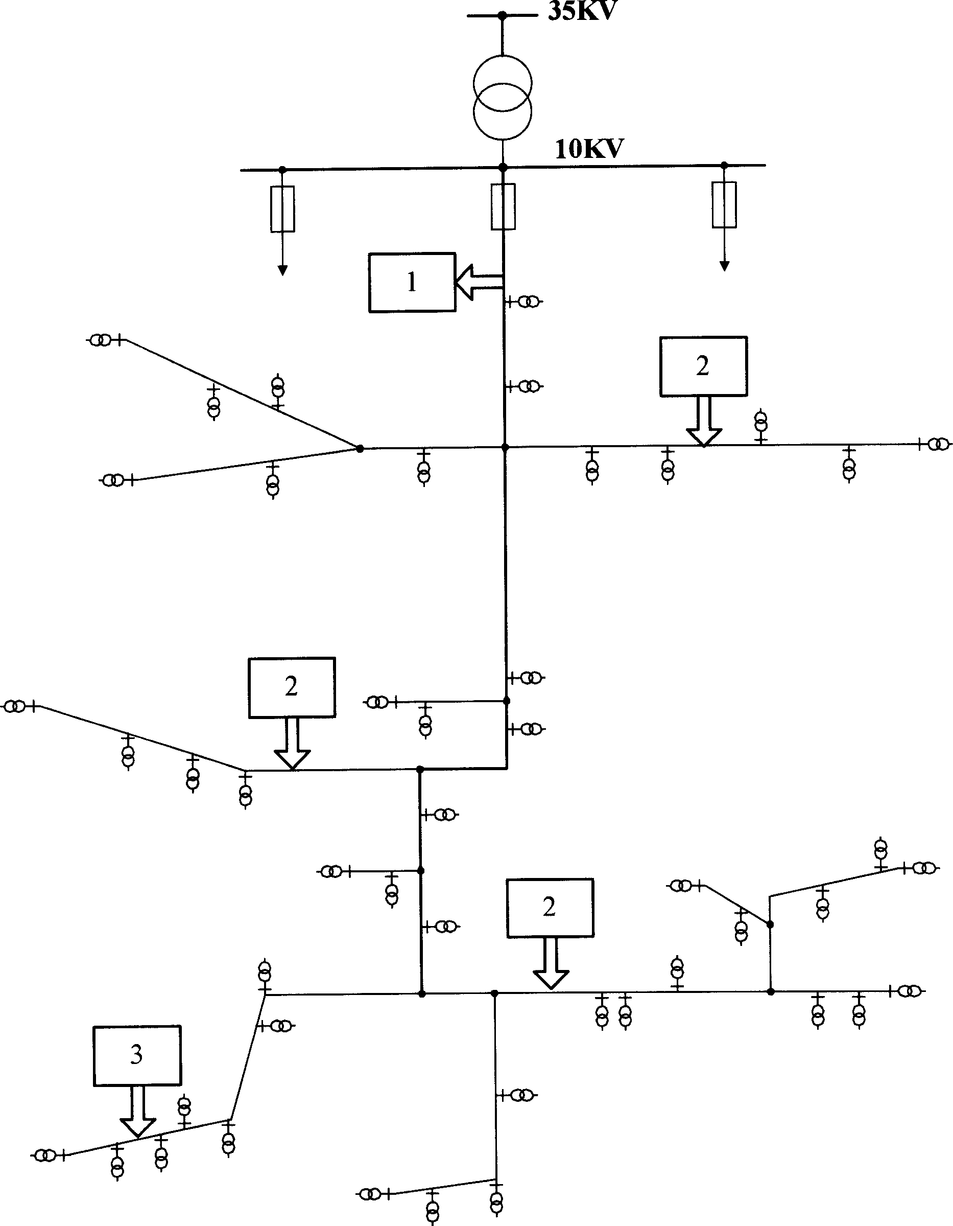
[0011] Embodiment 1: see attached figure 1 , a power grid reactive power compensation device, including a measurement control unit 1, one or more switching and reactive power compensation units 2, the measurement control unit 1, the switching and reactive power compensation unit 2 all have a The wireless data transmission unit 13, 21, the measurement control unit 1 calculates the reactive power or voltage based on the measured grid line voltage and current value as a control basis, and sends a control command through the wireless data transmission unit 13, and the switching And the reactive power compensation unit 2 accepts the control instruction through the wireless data transmission unit 21 and executes it.
Embodiment 2
[0012] Embodiment 2: see attached figure 1 , in the grid reactive power compensation device described in Embodiment 1,
[0013] The wireless data transmission units 13 and 21 transmit data using time-division frequency hopping technology;
[0014] The controller 12 of the measurement control unit 1 is a DSP240 single-chip microcomputer, and the program memory adopts 2764 chips; the input signal adopts AC sampling 11, the three-phase voltage is transformed by PT, and the three-phase current is transformed by CT, and becomes a voltage signal on the standard resistance , and then sent to the multi-channel switch through RC smoothing filter, and sent to the A / D port of the DSP240 single-chip microcomputer through gain amplification; the sampling frequency is 128 points per cycle, and the I / O output control command of the DSP240 single-chip microcomputer;
[0015] The compensation capacitor banks 22 of the switching and reactive power compensation unit 2 are grouped in a ratio of ...
Embodiment 3
[0016] Embodiment 3: see attached figure 1 , in the grid reactive power compensation device described in Embodiment 1 or 2, the measurement control unit 1 further includes:
[0017] A parameter setting module 14, to automatically set and manually set different control parameters such as reactive power, voltage, power factor, and time with dynamic tracking;
[0018] A statistical module 15, to count the total commissioning time, capacitor bank commissioning time, capacitor bank commissioning times or commissioning rate, etc.;
[0019] A display module 16 to display operating parameters, working status, protection status, etc.;
[0020] A communication module 17 to realize remote operation data transcription and monitoring.
PUM
 Abstract
Description
Claims
Application Information
 - R&D
- Intellectual Property
- Life Sciences
- Materials
- Tech Scout
- Unparalleled Data Quality
- Higher Quality Content
- 60% Fewer Hallucinations
Browse by: Latest US Patents, China's latest patents, Technical Efficacy Thesaurus, Application Domain, Technology Topic, Popular Technical Reports.
© 2025 PatSnap. All rights reserved.Legal|Privacy policy|Modern Slavery Act Transparency Statement|Sitemap|About US| Contact US: help@patsnap.com