Flash lamp control circuit

A technology for controlling circuits and flashes, applied in TV, optics, light sources, etc., to solve problems such as affecting image quality, insufficient, over-exposure exposure, etc.

Inactive Publication Date: 2010-05-05
IMPRESS ENTERPRISE
View PDF4 Cites 0 Cited by
  • Summary
  • Abstract
  • Description
  • Claims
  • Application Information

AI Technical Summary

Problems solved by technology

However, with the improvement of pixels, precise flash control technology will be an important factor affecting image quality, otherwise it is easy to cause overexposure or underexposure and affect image quality

Method used


Image

  • Flash lamp control circuit
  • Flash lamp control circuit
  • Flash lamp control circuit

Examples


Embodiment Construction

[0069] With regard to the features and practice of the present invention, preferred embodiments are described in detail with reference to the accompanying drawings.

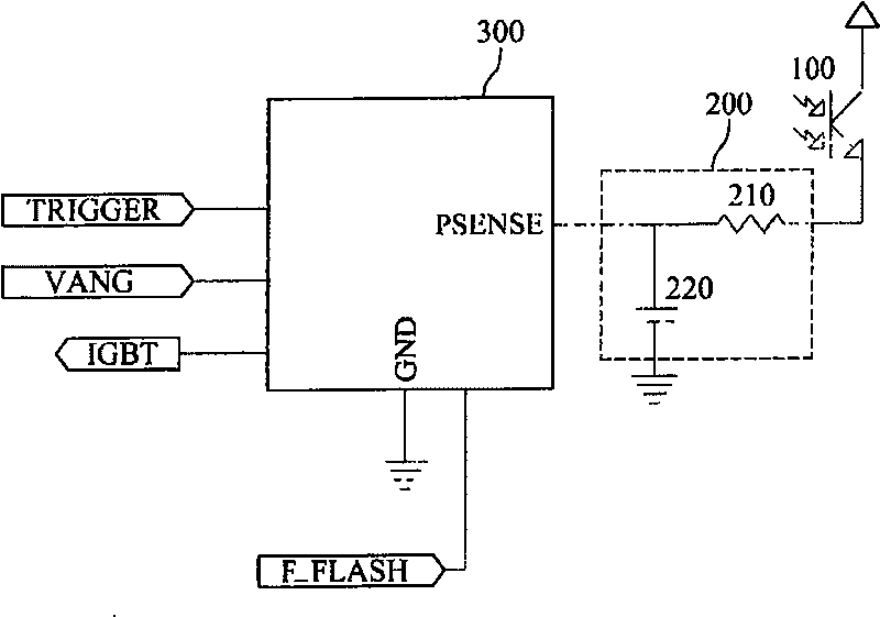
[0070] refer to figure 1 , is a structural diagram of the flashlight control circuit disclosed in the present invention. Because the characteristics of the phototransistor have high sensitivity to light, its emitter current has a good linear relationship to the light input, and the response time is fast, so the flash control circuit disclosed in the present invention uses a phototransistor to detect the reflected light of the subject Strength of.

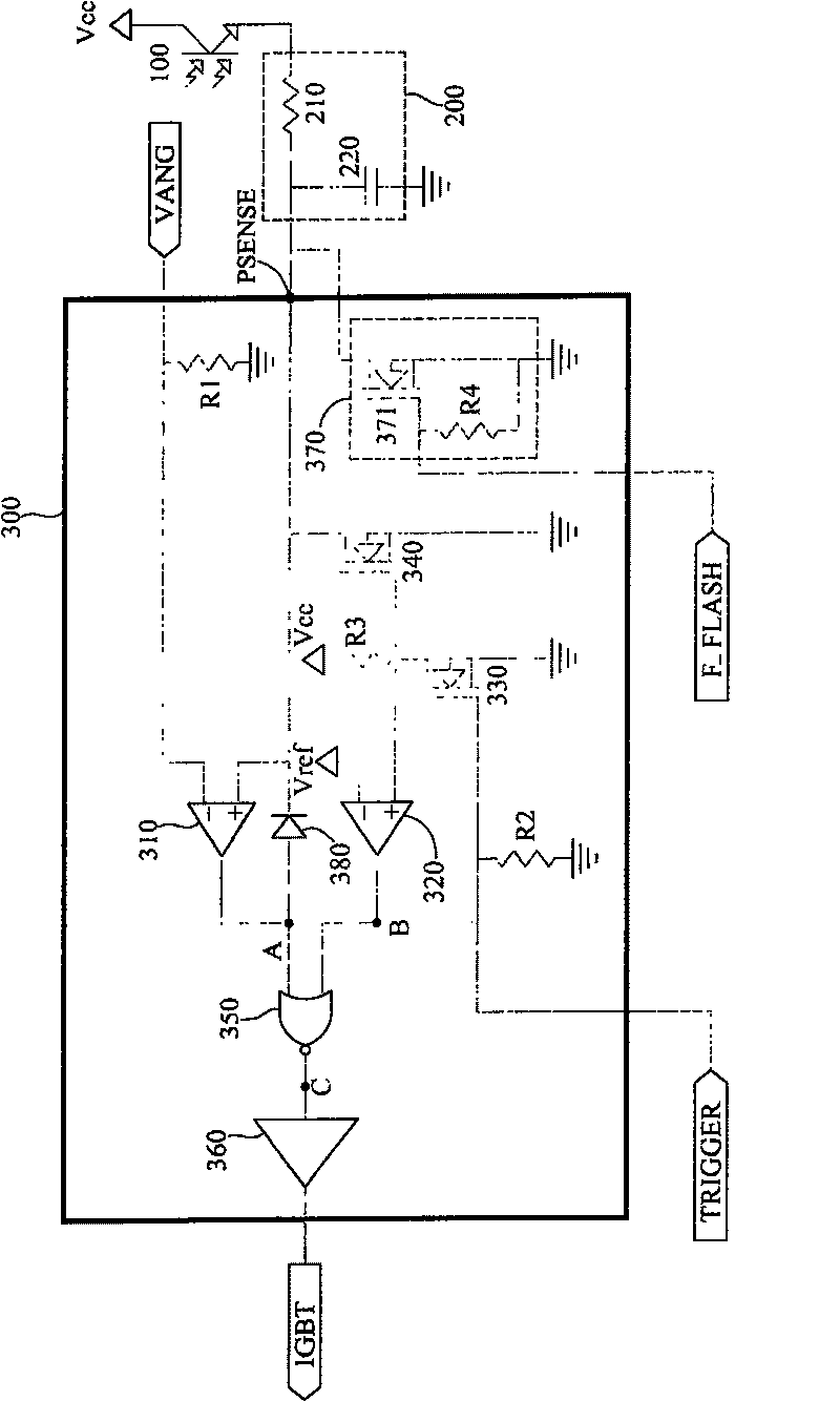
[0071] Such as figure 1 As shown, the flash control circuit disclosed in the present invention is composed of a phototransistor 100 , a brightness sensing circuit 200 and a trigger circuit 300 . The brightness sensing circuit 200 is composed of a resistor 210 and a capacitor 220 . The trigger circuit 300 is a circuit mainly composed of a metal oxide semiconductor f...


PUM


Abstract

The invention relates to a flash lamp control circuit, which can control the illumination according to the sensitive voltage and preset voltage. Said control circuit is formed by the first comparer, the second comparer and a logic gate; or formed by a comparer, the first reverse device, the first crystal tube, the first logic gate and the second logic gate. The invention can instantly discharge the capacitor without additional control signal when the trigger signal is stopped. And it can also comprise a clamp circuit, which can clamp the sensitive voltage lower than preset voltage according toa full-flash signal.

Description

technical field [0001] The invention relates to a flashlight control circuit, in particular to a flashlight control circuit which utilizes the photosensitive characteristics of a photosensitive transistor to reduce the brightness error value of a single machine after several brightness tests. Background technique [0002] With the advancement of digital image processing technology and Charge Coupling Device (CCD, Charge Coupling Device), digital cameras have become general consumer electronic products. Due to many factors such as computer penetration rate and ever-changing digital technology, more and more applications of digital cameras have been produced, which has accelerated our life towards digitalization. [0003] A flash is an essential component of a camera, whether it is a traditional camera or a digital camera. The operation of the current flash includes two stages: preflash and main flash. The preflash is mainly to judge the brightness of the object to be photogr...

Claims


Application Information

Patent Timeline
Patent Type & Authority Patents(China)
IPC IPC(8): H05B41/38G03B15/05H04N5/238
Inventor 朱益杉庄明男
Owner IMPRESS ENTERPRISE
Why Eureka
Try Eureka