Vacuum belt type filter and dehydration machine

A vacuum belt filter and dehydrator technology, applied in the direction of filtration separation, mobile filter element filter, separation method, etc., can solve the problems of poor adaptability to different solid content rates, large contact area, large power consumption, etc., and achieve low water content efficiency, reduce friction, and save energy

Inactive Publication Date: 2006-10-11
ZHEJIANG UNIV
View PDF0 Cites 19 Cited by
  • Summary
  • Abstract
  • Description
  • Claims
  • Application Information

AI Technical Summary

Problems solved by technology

Then, because the vacuum chamber of the traditional vacuum belt filter is completely composed of the rubber belt and the supporting object through water sealing, the rubber belt and the supporting body are in direct contact, the contact area is large, the

Method used


Image

  • Vacuum belt type filter and dehydration machine
  • Vacuum belt type filter and dehydration machine

Examples


Embodiment Construction

[0012] The present invention will be further described below in conjunction with drawings and embodiments.

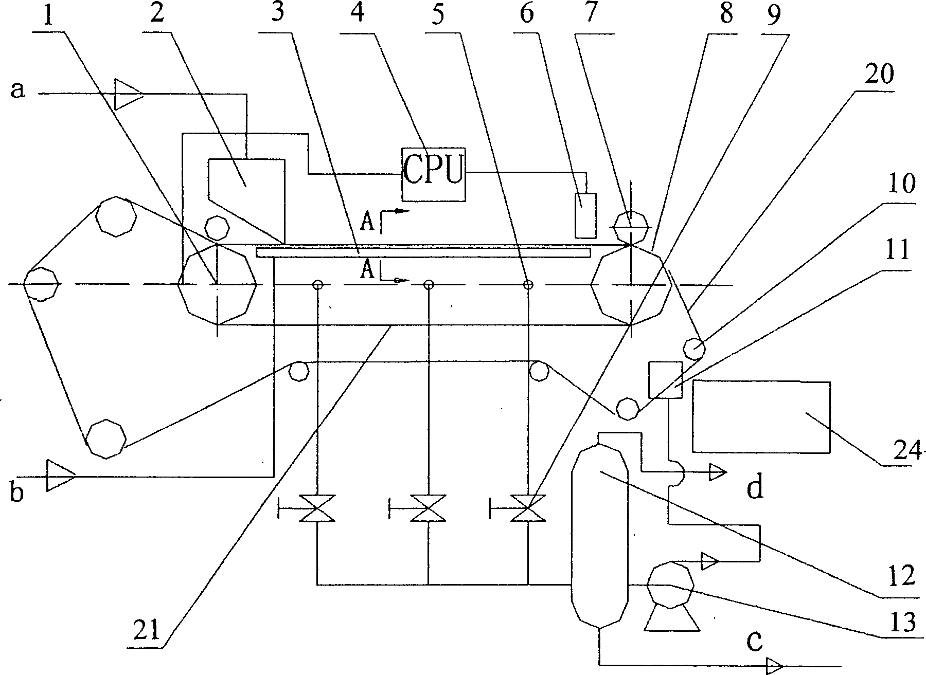
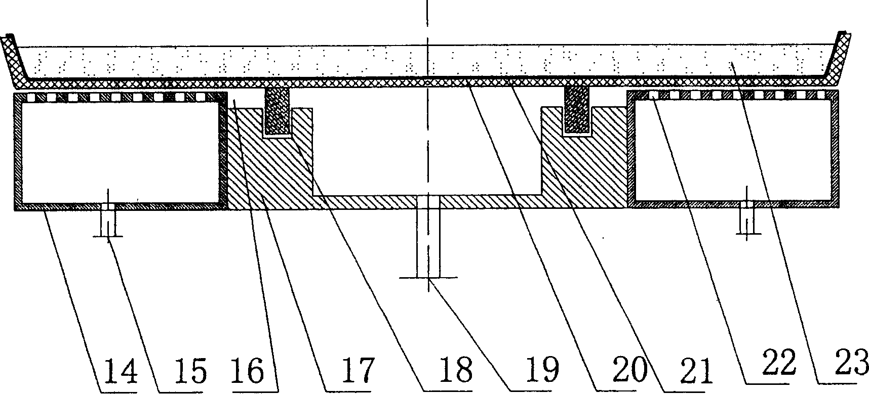
[0013] like figure 1 , figure 2 As shown, the present invention includes: the filter belt 20 is closely attached to the rubber belt 21 with corrugated grooves, the stock solution distributor 2 is installed above the filter belt 20, and 23 is the stock solution, and the filter belt is installed below the rubber belt 21 with corrugated grooves. The support system 3, the filter belt support system 3 is composed of a vacuum chamber 17 and a compressed air chamber 14 with a compressed air through hole 22 on the upper end. The two compressed air chambers 14 are respectively located on both sides of the vacuum chamber 17; the compressed air The inlet b is connected to the compressed air chamber 14 through the valve and the compressed air inlet 15, the steam-water separation tank 12 is connected to the vacuum chamber 17 through another valve 9 and the vacuum suction pipe 5, a...


PUM


Abstract

The invention discloses a vacuum belt filter dewaterer. Wherein, the filter belt is adhered on the rubber belt of ripple groove that driven by the drive motor as the rubber belt to step for the same direction; the rubber belt ripple groove is connected to the vacuum room; the rubber belt is supported by two lubricative support blocks and sealed by water, while said two support blocks and rubber belt form the vacuum room; the rubber belt outside the vacuum room is aerial via the compressed air when in working to reduce the friction resistance; the filter cake is compressed and dewatered at the front of outlet to attain drier filter cake and reduce the energy for following drying; the filter screen can execute filtration after regeneration. The invention has the advantages that: it uses vacuum filtration, with large filter drive power; the filter cake is mechanically compressed with lower moisture percentage; it can automatically detect the thickness of filter cake, via which to control the speed of filter belt to confirm the uniformity of filter cake; it has lower demand for the solid content of filter liquid; and it can realize continuous operation with high automatic degree and better economic benefit.

Description

technical field [0001] The invention relates to a solid-liquid separation device for removing solid particles in a liquid phase, in particular to a vacuum belt filter dehydrator. Background technique [0002] The traditional vacuum belt filter has been widely used in various fields of industry and agriculture, and has always had a large market share due to its simple structure, low price, and high efficiency. Then, because the vacuum chamber of the traditional vacuum belt filter is completely composed of a rubber belt and a supporting object through a water seal, the rubber belt and the supporting body are in direct contact, the contact area is large, the friction is large, and the power consumption is large. Traditional filters have poor adaptability to different solid content rates, and generally can only be adjusted by continuously adjusting the belt speed to adapt to changing solid content rates. Aiming at the above shortcomings, the present invention proposes a vacuum ...

Claims


Application Information

Patent Timeline
IPC IPC(8): B01D33/04B01D33/056
Inventor 郑传祥雷绍辉
Owner ZHEJIANG UNIV
Why Eureka
Try Eureka