Eureka AIR delivers breakthrough ideas for toughest innovation challenges, trusted by R&D personnel around the world.

Thawing stripping type ice making apparatus

A detachment and hot-melt technology, applied in ice making, ice making, lighting and heating equipment, etc., can solve the problems of uneven thickness of flake ice, large power consumption, slow ice making speed, etc., and achieve high utilization rate of evaporation area , prolong the service life and improve the ice storage rate

Inactive Publication Date: 2006-10-11
NINGBO UNIV
View PDF1 Cites 17 Cited by
  • Summary
  • Abstract
  • Description
  • Claims
  • Application Information

AI Technical Summary

Problems solved by technology

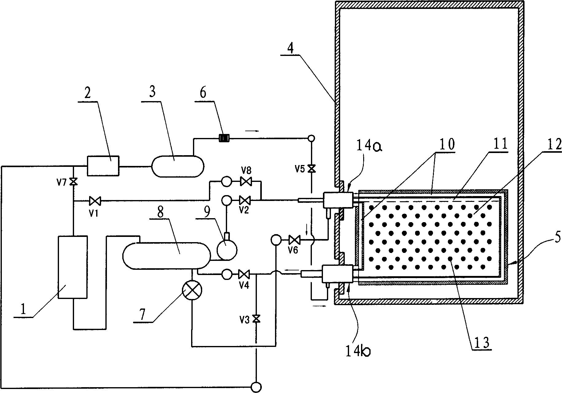
Obviously, such a structure will cause the following defects: (1) During the ice-making process, the water pump needs to work continuously, so it consumes a lot of electric energy, and because of accessories such as water dispensers and water pumps, there are many parts in the device and the pipeline is complicated
(2) Since the water freezes during the falling process on the surface of the evaporator, the ice-making speed is slow, and the thickness of the flake ice produced is uneven
(3) When flakes of ice collide with each other or collide with the slant plate during the falling process, it is inevitable that there will be noise and broken ice, and the broken ice reduces the ice storage rate, and at the same time it is easy to block the filter.
(4) Since the falling off of flake ice requires a large space, it will cause the disadvantages of large volume and low utilization rate of the ice storage tank
(5) The position of the evaporator is high, so it is inconvenient to install
(6) Since the evaporator is only provided with a single refrigerant channel, when the ice layer reaches a certain thickness, it is easy for the flake ice on each side of the evaporator to be connected and unable to fall off

Method used


Image

  • Thawing stripping type ice making apparatus
  • Thawing stripping type ice making apparatus
  • Thawing stripping type ice making apparatus

Examples


Embodiment 2

[0029] Example 2, such as Figure 5 and Figure 6 As shown, it differs from the above-mentioned first embodiment in that the evaporating plate is wound by a serpentine tube to form the refrigerant low-pressure liquid channel 12, and a circle of tubes is surrounded around the serpentine tube to form The thermal fluid channels 10 are connected to each other as a whole through metal fins 19 between adjacent tubes. Its working principle is the same as that of the above-mentioned first embodiment, and will not be described in detail here.

Embodiment 3

[0030] Example 3, such as Figure 7 As shown, it differs from the above-mentioned first embodiment in that the evaporating plate is wound by a serpentine tube to form the refrigerant low-pressure liquid channel 12, and the serpentine tube is surrounded by a circle and adjacent The pipes connected by the serpentine pipes form the thermal fluid channel 10, and the two sides of the serpentine pipes are respectively covered with metal sheets 20, and the cavity formed between each metal sheet and the serpentine pipes is filled with thermal fluid. Make the heat transfer effect better.

Embodiment 4

[0031] Example 4, such as Figure 8 As shown, it differs from the above-mentioned first embodiment in that: there is air in the hot fluid channel 10, and the air can be outdoor air or hot air, as long as its temperature is higher than the freezing temperature. In this way, driven by the blower fan 21 , the air continuously flows in the thermal fluid channel 10 , and the sensible heat of the air is used to separate the ice flakes on both sides. In this embodiment, the air can also be replaced by hot water or steam or antifreeze. At the same time, the refrigerant coming out of the filter drier 6 enters the low-pressure liquid receiver 8 after passing through the regenerator 22 and the thermal expansion valve 7. In this way, the heat exchange between the condensate and the suction air of the compressor is carried out through the regenerator 22 , thereby increasing the suction air temperature and working efficiency of the compressor 1 .

[0032] When the above-mentioned ice makin...


PUM


Abstract

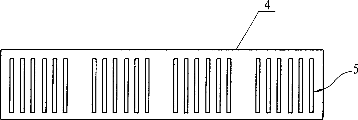
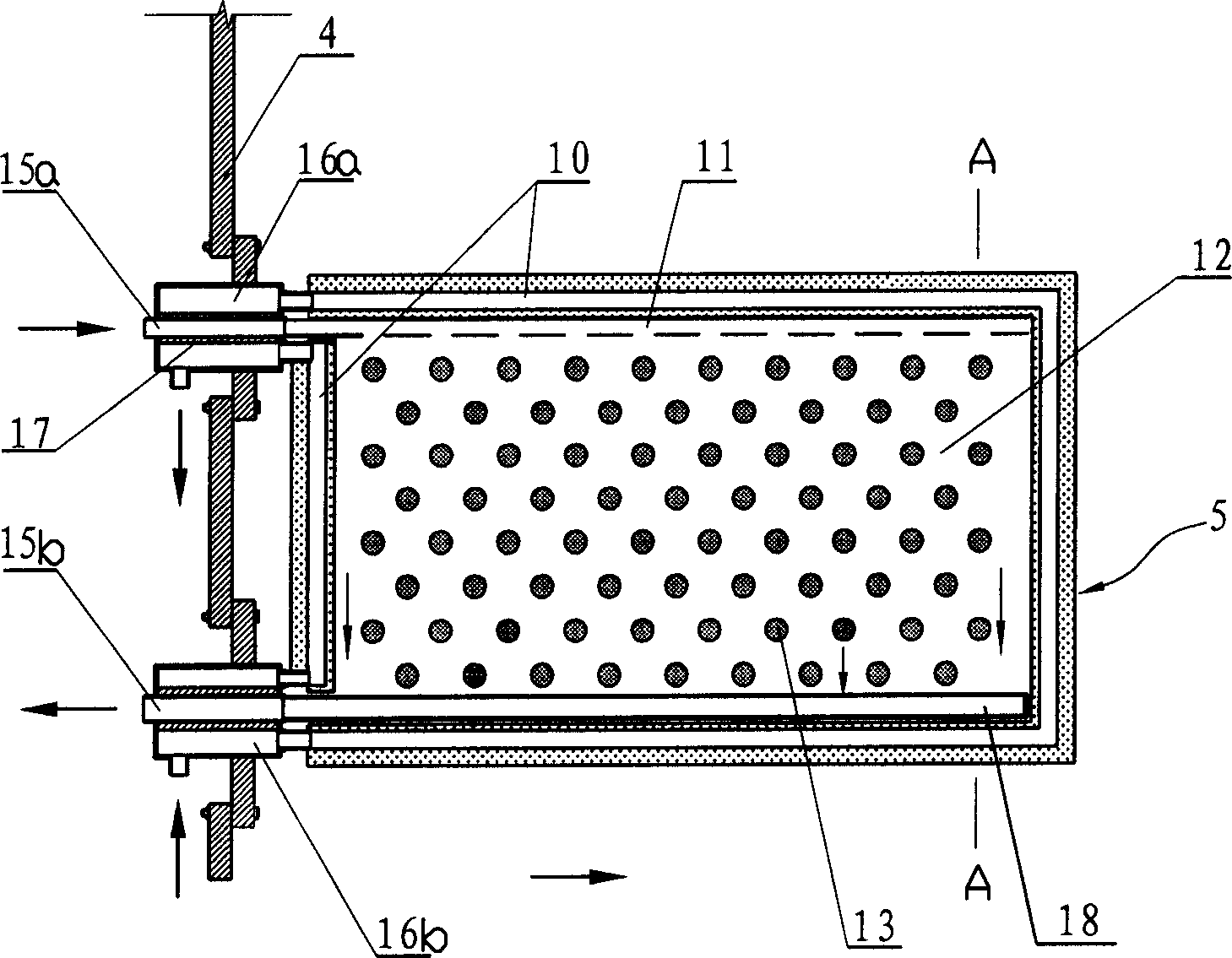
The invention discloses a fusible removing icing device, which is based on the former refrigerating circuit, heat de-ice circuit and the ice groove. Wherein, the ice groove also contains water; the evaporator of said refrigerating circuit is mounted inside the ice groove and dipped into the water; the interfaces of each side surface of evaporator have the heat conductors connected to the ice. With said invention, the circuit is simple, with lower electricity consumption, high icing speed, uniform ice thickness and non noise. In addition, the position of evaporator is lower to apply mounting; the evaporator has heat conductors as electric heating element or coolant high-pressure solution flowing in the hot liquid channel, air, hot water, steam, or antifreeze solution whose heat can make the temperature at the interfaces higher than icing temperature, to avoid connection of ices.

Description

technical field [0001] The invention relates to an ice-making device, in particular to a heat-melting and falling-off type ice-making device Background technique [0002] Flake ice is widely used in the fields of food preservation, air-conditioning cold storage and industrial production because of its large surface area, low energy consumption and convenient use. At present, the flake ice is usually produced by a mechanical scraping ice-making device or a hot-melt-off ice-making device. The ice layer falls off from the wall of the evaporator, as disclosed in "An Ice Maker" with Chinese Patent No. 200420046820.6, which discloses such a heat-melting and falling-off type ice-making device, which includes a refrigeration pipeline, which is connected to the refrigeration pipeline. The thermal deicing branch circuit and water supply assembly, the refrigeration circuit includes a compressor, condenser, expansion valve and evaporator. connected to the evaporator. When in use, ref...

Claims


Application Information

Patent Timeline
IPC IPC(8): F25C1/12F25C1/08
Inventor 杨国华吴伯才
Owner NINGBO UNIV
Why Eureka
Eureka Blog
Learn More