Method for monitoring film thickness of optical filter

A technology of film thickness and optical film, applied in optical filters, special data processing applications, instruments, etc., can solve problems such as inconvenient compensation of coating errors, thickness differences, and control accuracy problems, and achieve manual control and automatic control Optimize, reduce the amount of calculation, improve the effect of control accuracy

Active Publication Date: 2006-11-15
上海欧菲尔光电技术有限公司 +1
View PDF0 Cites 8 Cited by
  • Summary
  • Abstract
  • Description
  • Claims
  • Application Information

AI Technical Summary

Problems solved by technology

Its disadvantages are: when the film is coated to a thicker thickness, the monitoring optical signal will be deformed; the error caused by the change of the coating state cannot be easily compensated
The disadvantage is that when the sample to be plated is deposited to a certain thickness and a new monitoring sheet is replaced, there is a significant difference between the thickness of the film layer dep

Method used


Image

  • Method for monitoring film thickness of optical filter
  • Method for monitoring film thickness of optical filter
  • Method for monitoring film thickness of optical filter

Examples


Example Embodiment

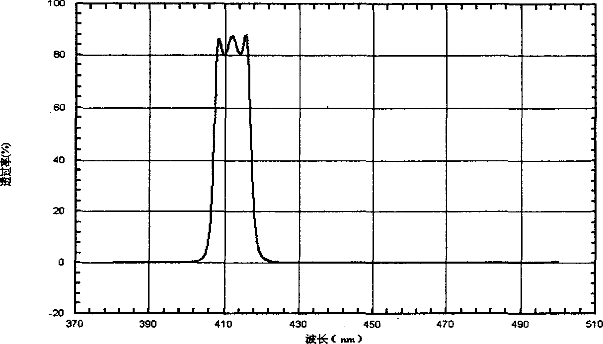
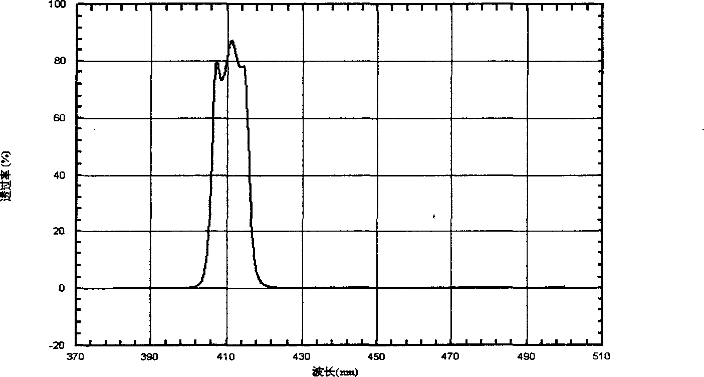
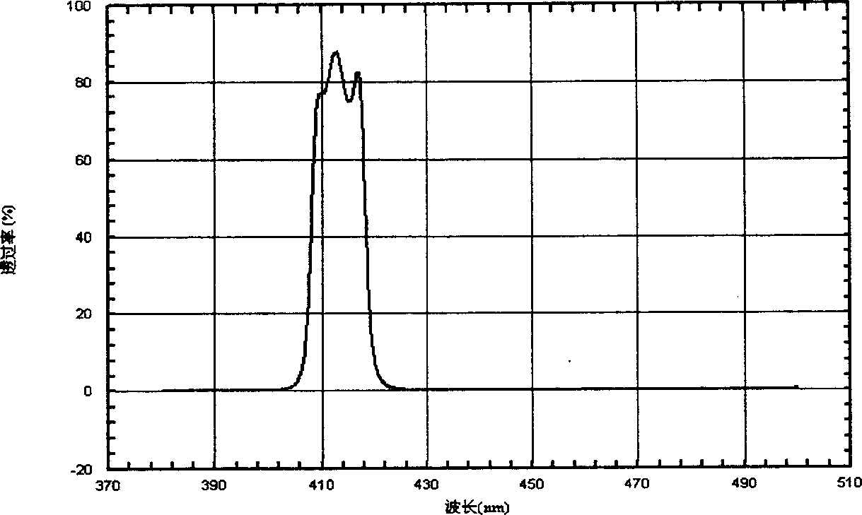
[0031] Example 1: 412nm narrow-band filter with a bandwidth of 20nm. The film system of the three-half-wave narrow-band filter is (LHLH2LHLH)3, L is SiO2, H is TiO2, and 3 monitors are selected, and the film system of each control film For LHLH2LHLH, the monitoring film adopts Si, and the indirect control method of reflective optical extreme value is used to monitor the film thickness. The preparation of the optical film of the filter is carried out according to the above steps. figure 2 It uses the optical film design Filmward software to simulate and analyze the calculated spectral curve. figure 2 The three calculation curves in the middle represent the different effects brought about by the change of the monitoring wavelength of the three monitoring chips if there is no error in the monitoring and no change in the evaporation state. figure 2 The calculation curve of (a) simulates that the monitoring wavelengths of the three monitoring chips are the same, and there is no chan...

Example Embodiment

[0032] Example 2: Infrared cut filter, its requirement is 420-600nm, transmittance is greater than 85%, λ=645nm, T=50%, 700-1050nm, T 平均 最大 <10%. The membrane system is designed as two cut-off membrane stacks, and the membrane system is: 1.214L 1.118H 1.123L.996H 1.074L.957H1.06L.963H 1.056L.96H 1.054L.966H 1.064L.972H 1.073L 1H 1.11L 1.07H 1.23L1.264H 1.355L 1.322H 1.371L 1.326H 1.362L 1.317H 1.37L 1.34H 1.389L 1.354H1.397L 1.352H 1.383L 1.315H 1.299L 1.142H.58L.

[0033] Monitoring wavelength λ 0 =735nm, L-SiO2, H-TiO2.

[0034] Therefore, six monitoring films are used, and each of the first five monitoring films is coated with 6 layers of film. The film system of the monitoring films is:

[0035] The first monitoring film: 1.214L 1.118H 1.123L.996H 1.074L.957H;

[0036] The second monitoring film: 1.06L.963H 1.056L.96H 1.054L.966H;

[0037] The third monitoring film: 1.064L.972H 1.073L 1H 1.11L 1.07H;

[0038] The fourth monitoring film: 1.23L 1.264H 1.355L 1.322H 1.371L 1.326H...


PUM


Abstract

The present invention discloses a monitoring method of optical filter film thickness. Said method includes the following steps: firstly, calculating spectral curve of every monitoring film using central wavelength lambda O as monitoring wavelength; calculating series spectral curve using out-of-centre wavelength as monitoring wavelength; then using conventional extreme indirect monitoring method to plate optical film on substrate; testing the spectral curve of plated filter; comparing the tested spectral curve with analogously-calculated spectral curves to find out most similar spectral curve in the calculated spectral curves, regulating monitoring wavelength and preparing new filter again, repeating the above-mentioned steps until the waveform and transmittance or reflectance indexes spectral curve of filter are reached to indexes of designed requirements.

Description

Technical field [0001] The invention relates to the field of optical films, in particular to a method for monitoring the film thickness of an optical filter. technical background [0002] The optical filter is composed of a substrate and a vacuum evaporation optical film system on the substrate. When the optical film is deposited, the reflected and transmitted light will change due to the change of the thickness of the film. Therefore, it is most appropriate to use the change of the optical signal to control the change of the thickness of the film. The commonly used optical film thickness monitoring methods are: the visual method to directly observe the color change of the film; the wavelength modulation method to measure the derivative change of the transmittance or reflectance with respect to the wavelength; to measure the extreme value change of the transmittance or reflectance of the film. Value method. [0003] The visual method uses the human eye as a receiver to visually o...

Claims


Application Information

Patent Timeline
IPC IPC(8): G02B5/20G06F17/50
Inventor 周东平
Owner 上海欧菲尔光电技术有限公司
Why Eureka
Try Eureka