Selectable ion concentrations with electrolytic ion exchange

A technology of ion concentration and cation exchange, which is used in the field of processing influent liquid containing ions, which can solve the problems of uncontrollable ion concentration and so on.

Active Publication Date: 2006-11-15
POS TECH INC
View PDF1 Cites 21 Cited by
  • Summary
  • Abstract
  • Description
  • Claims
  • Application Information

AI Technical Summary

Problems solved by technology

[0005] Moreover, conventional electrolytic ion exchange systems cannot yet control ion concentration

Method used


Image

  • Selectable ion concentrations with electrolytic ion exchange
  • Selectable ion concentrations with electrolytic ion exchange
  • Selectable ion concentrations with electrolytic ion exchange

Examples


Embodiment 1

[0076] Example 1: Constant Voltage

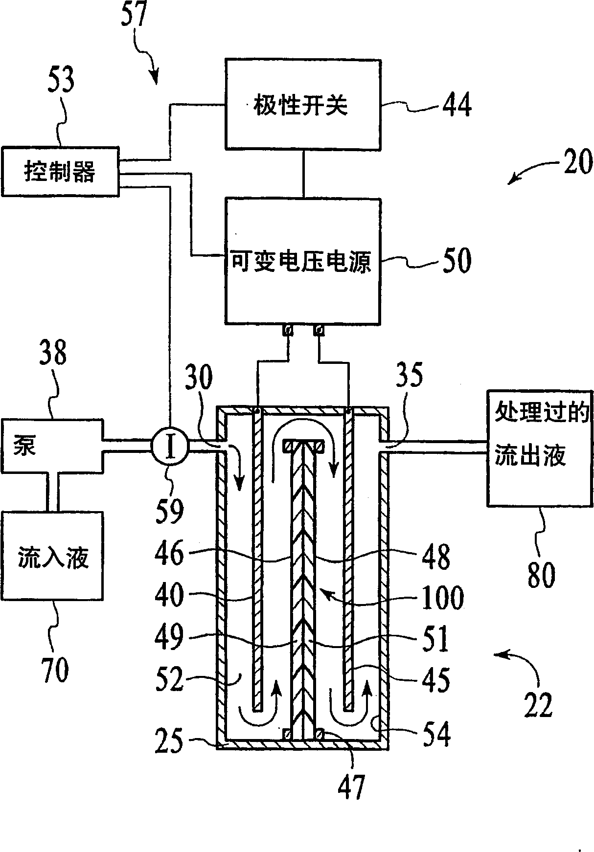
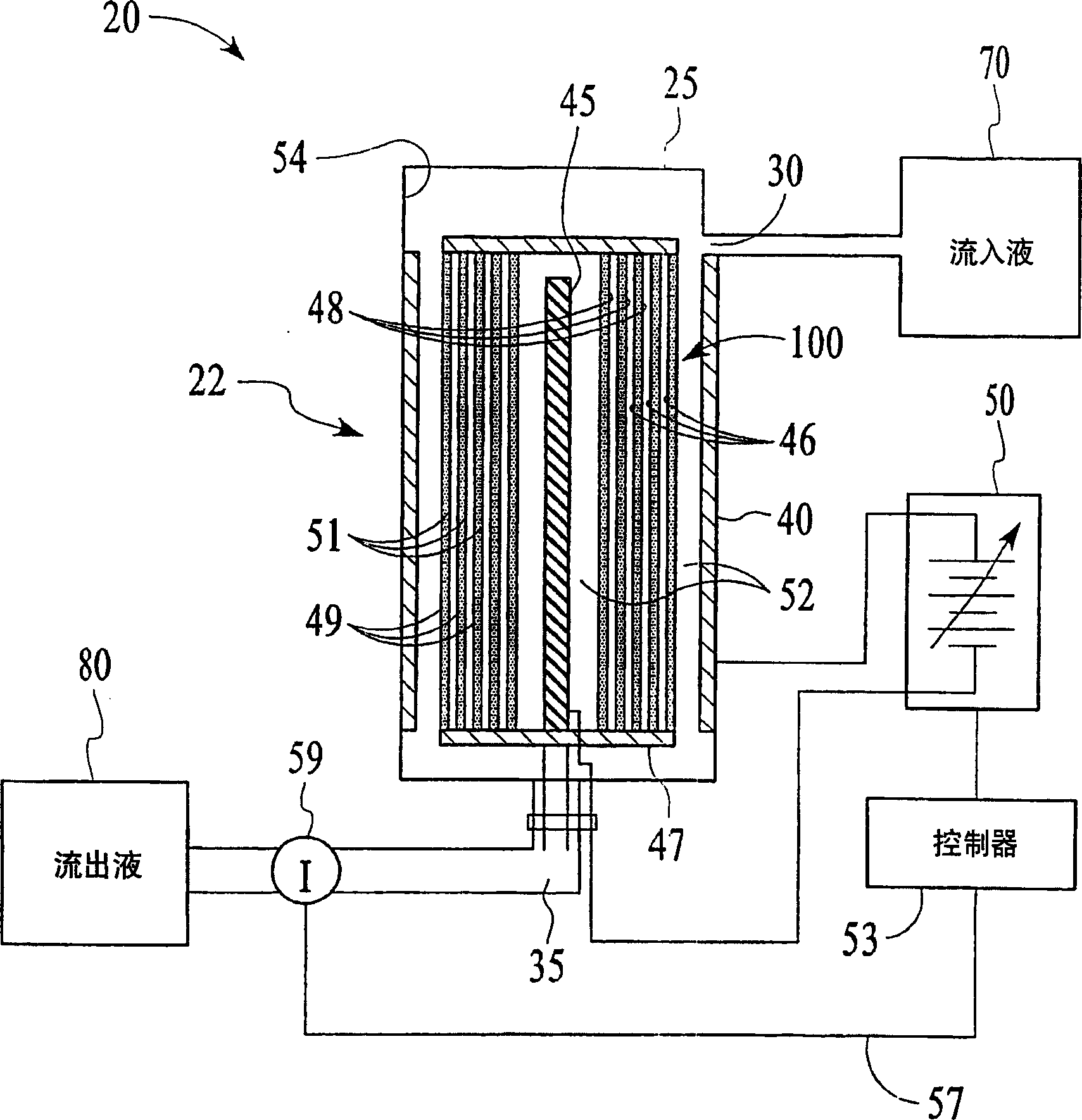
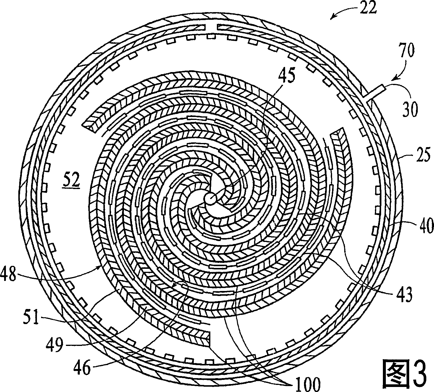
[0077] This embodiment typically measures the loss of ion removal efficiency of the hydrolyzed ion exchange membrane 100 in one ion removal cycle. The TDS content reduction test was conducted using a cell 22 including a helically wound hydrolysis membrane 100 in a cylindrical casing 25 . A constant voltage power supply with a current limit of 1A is used, so no feedback circuit is used. Cell 22 includes 30 layers of membrane 100 between a center electrode and an outer electrode. Membrane 100 has cation exchange layer 51 facing outward and anion exchange layer 49 facing inward. Initially, cell 22 was regenerated by a 20-minute ion exclusion step at 160 ml / min and 300 V using a feed water flow of ~50 μS / cm to prepare it for a deionization or ion removal step. During this regeneration step, the current to the electrodes 40 , 45 is maintained at 0.5-1.0 amps, and the influent 70 flows from the inside to the outside of the spiral membrane 100 ...

Embodiment 2

[0079] Example 2: Variable Voltage

[0080] In this embodiment, the device 20 includes the battery 22 of Embodiment 1 with an ion sensor 59 that is connected to a controller 53 (which includes a microprocessor to interpret the ion concentration signal and to control the output voltage of the variable voltage power supply 50). ) connected conductivity sensor. The target ionic conductivity for this test is 125 μS / cm. A preliminary test determines the output voltage for different deviations of the 80 ionic conductivity of the effluent from the target conductivity. The results are shown in Figure 11 variable voltage curve. When the measured conductivity exceeds the target of 125 μS / cm, the controller 53 increases the voltage of the cell 22 and the conductivity of the effluent 80 decreases shortly thereafter. The slow rise and fall changes of effluent 80 are a result of the finite response time of the system. This depends primarily on the flow rate and void volume of the cell...


PUM


Abstract

An apparatus (20) treats an influent solution (70) comprising ions to obtain a selectable ion concentration in an effluent solution (80). The apparatus (20) comprises an electrochemical cell (22) comprising a housing (25) comprising first and second electrodes (40, 45). A water-splitting ion exchange membrane (100) is between the first and second electrodes (40, 45), the membrane (100)comprising an anion exchange surface (46) facing the first electrode (40), and an cation exchange surface (48) facing the second electrode (45), or vice versa. The housing (25) also has an influent solution inlet (30) and an effluent solution outlet (35) with a solution channel (52) that allows influent solution (70) to flow past both the anion and cation exchange surfaces (46, 48) of the water-splitting ion exchange membrane (100) to form the effluent solution (80). A variable voltage supply (50) is capable of maintaining the first and second electrodes (40, 45) at a plurality of different voltages during an ion exchange stage.

Description

Background technique [0001] The practice of the present invention relates to ion exchange methods and apparatus. Ion exchange cells are used to remove or replace dissolved solids or ions in a solution. For example, ion exchange membranes and ion exchange beads are used to deionize water to produce high purity drinking water by removing pollutants and other dissolved solids in municipal wastewater streams. Ion exchange is also used for the selective replacement of ions in industrial wastewater treatment. In another example, tap water is softened by replacing hard divalent ions such as calcium in the tap water with soft monovalent ions such as sodium or potassium. Typically, ion exchange efficiency is measured by determining the total dissolved solids (TDS) content of treated and untreated solutions and expressed as a percent reduction (%R). [0002] Electrolytically assisted ion exchange increases ion extraction efficiency and facilitates regeneration of ion exchange materia...

Claims


Application Information

Patent Timeline
Patent Type & Authority Applications(China)
IPC IPC(8): C02F1/469B01D61/44B01D61/46B01D61/52B01D61/54B01D63/10B01J47/08B01J47/12B01J49/00C02F1/42
CPCB01D61/445B01D61/46B01D61/52B01D61/54B01D63/10C02F1/42C02F1/4693C02F2201/4613C02F2201/4616C02F2201/46175C02F2209/05C02F2303/16Y02W10/37B01J49/30
Inventor 吉姆·霍姆斯埃里克·尼伯格乔·埃文斯
Owner POS TECH INC
Why Eureka
Try Eureka