Tower plate with sinker in downcomer
A downcomer and energy dissipator technology, applied in chemical instruments and methods, distillation separation, separation methods, etc., can solve the problems of low vapor-liquid separation efficiency, increase equipment production costs, increase the height or diameter of tray towers, etc. Improve mass transfer efficiency and production efficiency, reduce height and diameter and cost, and increase the effect of residence time
- Summary
- Abstract
- Description
- Claims
- Application Information
AI Technical Summary
Problems solved by technology
Method used
Image
Examples
Embodiment 1
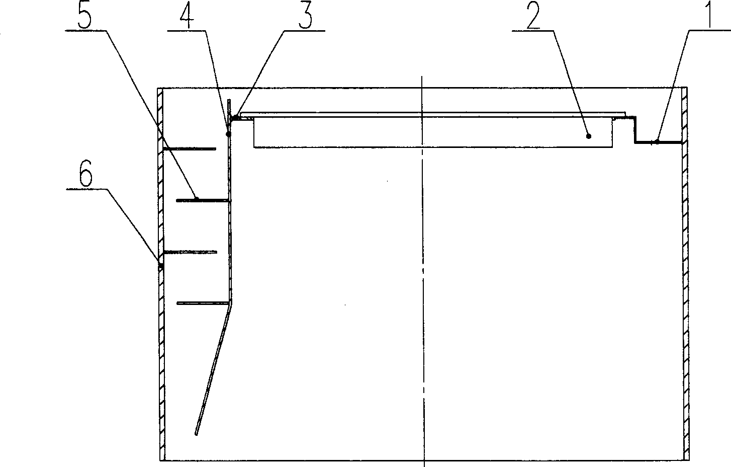
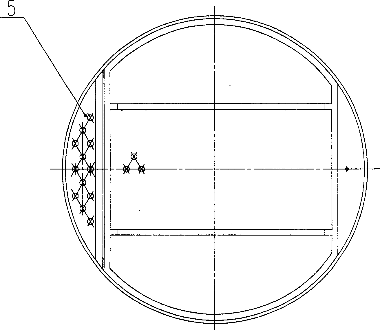
[0025] figure 1 , 2 A schematic structural diagram of Embodiment 1 of the present invention is given. exist figure 1 , 2 Among them, the tray with energy dissipator downcomer in this embodiment is composed of a liquid receiving tray 1 , a tray plate 2 , a support plate 3 , a downcomer plate 4 , a baffle plate 5 , and a tower body 6 .
[0026] A downcomer plate 4 is welded on the left side of the inner wall of the tower body 6, and a liquid receiving plate 1 is welded on the right side. The liquid receiving plate 1 is used to bear the liquid flowing down from the upper tray, and the downcomer plate 4 is welded with The support plate 3, the support plate 3 and the liquid receiving plate 1 are connected with a tray plate 2 with a threaded fastening joint, and the tray plate 2 is processed with holes, and the gas flows in from the lower part of the tower body 6, and the gas flows in from the tray plate 2. The holes flow to the tray plate 2 for mass transfer and heat transfer b...
Embodiment 2
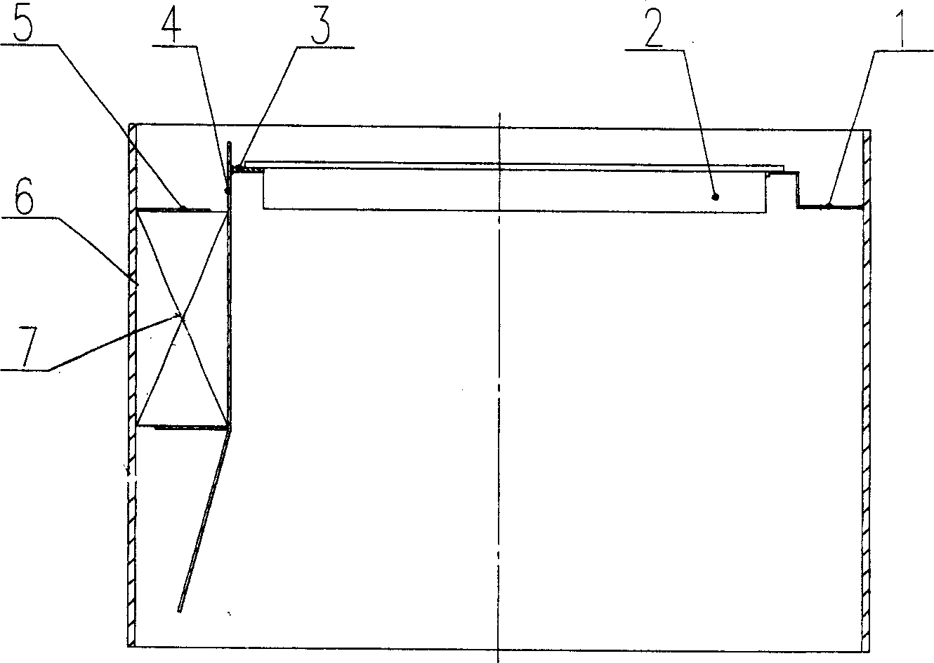
[0029] exist image 3 , 4 Among them, the tray with energy dissipator downcomer in this embodiment is composed of liquid receiving tray 1, tray plate 2, support plate 3, downcomer plate 4, baffle plate 5, tower body 6, and metal packing 7. . Two spoilers 5 are welded on the inner wall of the tower body 6 in the downcomer formed between the downcomer plate 4 and the tower body 6 and the downcomer plate 4 , and one spoiler plate 5 is welded on the inner wall of the tower body 6 , a baffle 5 is welded on the downcomer 4, the two baffles 5 are parallel to each other and arranged in a staggered manner, the baffle 5 is processed with flow-limiting holes with a diameter of 5 mm, and one flow-limiting hole is connected to the adjacent The center-to-center distance of a restrictor hole is 7.5mm. Welded on the inner wall of the tower body 6, the gap between the outer end of the baffle plate 5 and the downcomer plate 4 is 30% of the distance between the downcomer plate 4 at the positi...
Embodiment 3
[0031] In this embodiment, two baffles 5 are welded on the inner wall of the tower body 6 in the downcomer, two baffles 5 are welded on the downcomer 4, and the baffles welded on the inner wall of the tower body 6 5 and the baffles 5 welded on the downcomer 4 are alternately arranged. Welded on the inner wall of the tower body 6, the gap between the outer ends of the two baffle plates 5 and the downcomer plate 4 is 20% of the distance between the downcomer plate 4 at the position of the two baffle plates 5 and the inner wall of the tower body 6. The gap between the outer ends of the two baffles 5 on the downcomer 4 and the inner wall of the tower body 6 is 20% of the distance between the downcomer 4 and the inner wall of the tower body 6 at the positions of the two baffles 5 . The distance between one baffle 5 and the upper and lower adjacent baffles 5 is 20% of the height of the downcomer. One baffle 5 is parallel to the adjacent baffle 5 and parallel to the bottom surface o...
PUM
 Abstract
Description
Claims
Application Information
 - R&D Engineer
- R&D Manager
- IP Professional
- Industry Leading Data Capabilities
- Powerful AI technology
- Patent DNA Extraction
Browse by: Latest US Patents, China's latest patents, Technical Efficacy Thesaurus, Application Domain, Technology Topic, Popular Technical Reports.
© 2024 PatSnap. All rights reserved.Legal|Privacy policy|Modern Slavery Act Transparency Statement|Sitemap|About US| Contact US: help@patsnap.com


