Control apparatus for an eletric locomotive
一种电动车控制、电动车的技术,应用在电动汽车、机动车、控制驱动等方向,能够解决VVVF蓄能装置的容量不能被充分使用、吸收不能被持续下去、不能有效吸收等问题
- Summary
- Abstract
- Description
- Claims
- Application Information
AI Technical Summary
Problems solved by technology
Method used
Image
Examples
no. 1 example
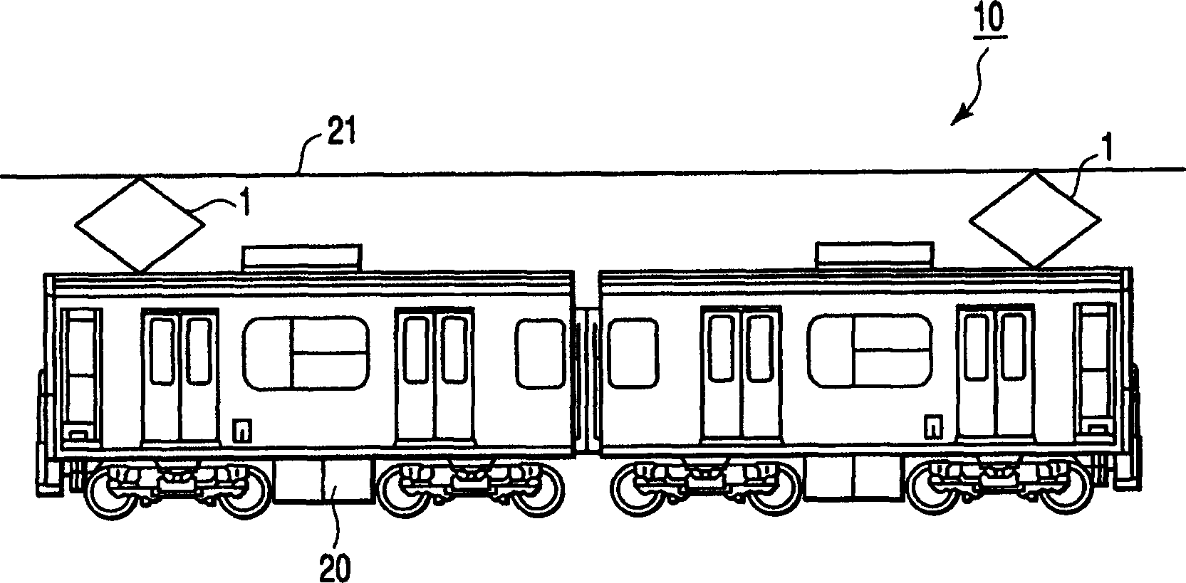
[0027] figure 1 is an external view showing an electric vehicle including the electric vehicle control apparatus according to the first embodiment of the present invention.
[0028] Such as figure 1 As shown in , the electric vehicle 10 receives power from the overhead line 21 through the pantograph 1 . The received electric power is input to the electric vehicle control device 20 .
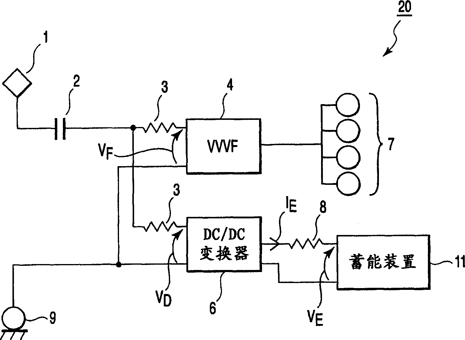
[0029] figure 2 is a block diagram showing the configuration of the electric vehicle control device 20 .
[0030] The electric vehicle control device 20 includes a pantograph 1 , a contactor 2 , a filter reactor 3 , a VVVF inverter 4 , a DC / DC converter 6 , a motor 7 , a reactor 8 , wheels 9 and an energy storage device 11 . Assume V F , V D and V E are the voltages applied to VVVF inverter 4, DC / DC converter 6 and energy storage device 11 respectively, I E is the current flowing from the DC / DC converter 6 to the energy storage device 11 .
[0031] The operation of the electric vehicle ...
no. 2 example
[0042] An electric vehicle control apparatus according to a second embodiment of the present invention will be described below with reference to FIGS. 6-8. The same reference numerals as in the first embodiment denote the same components in the second embodiment, and detailed description thereof will be omitted.
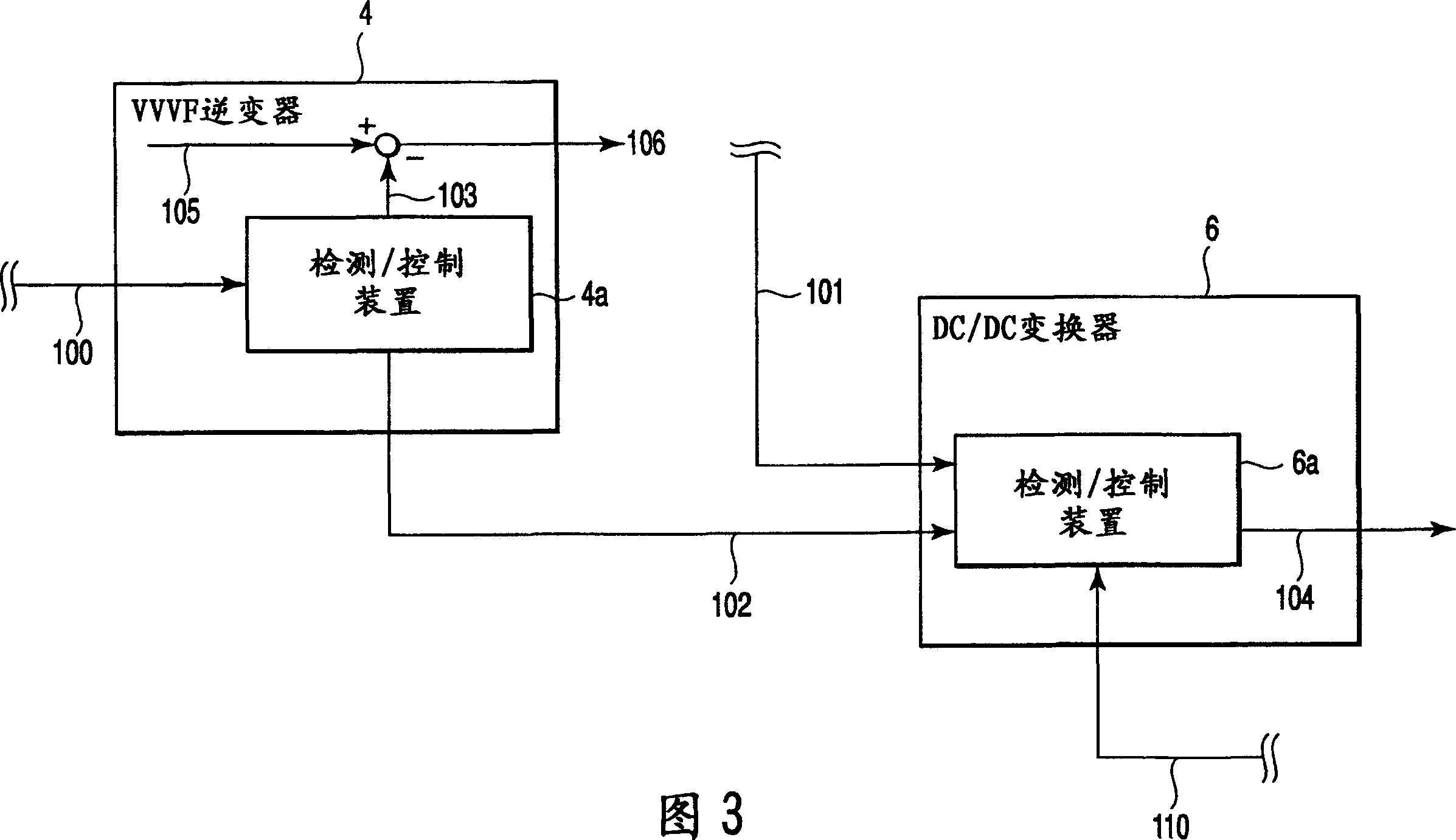
[0043]The difference between the second embodiment and the first embodiment is that the detection / control device 4a of the VVVF inverter 4 does not output any information to the detection / control device 6a of the DC / DC converter 6, and the DC of the energy storage device 11 The absorption starting voltage value V3 of the filter capacitor voltage value 101 of the / DC converter is set in advance to be equal to the operation starting voltage setting value (regeneration limiting starting voltage value) V1 of the filter capacitor voltage value 100 .
[0044] Figure 7 Shows the relationship between the regenerative braking throttle amount α and the operation starting vol...
no. 3 example
[0048] Refer below Figure 9 and 10 An electric control device according to a third embodiment of the present invention will be described. The same reference numerals as in the first embodiment denote the same components in the third embodiment, and detailed description thereof will be omitted.
[0049] The third embodiment differs from the first embodiment in that the information output from the detection / control device 4a of the VVVF inverter 4 to the detection / control device 6a of the DC / DC converter 6 is different from the regenerative braking throttle amount information 103.
[0050] The DC / DC converter 6 also includes a predetermined value detection unit 6b. The predetermined value detection unit 6b outputs a correction command for correcting the absorbing start-up voltage value V3 to a voltage value V3' to the detection / control device 6a of the DC / DC converter 6 according to the input regenerative braking restraint amount information 103 (see Figure 10 ). The pred...
PUM
 Abstract
Description
Claims
Application Information
 - R&D
- Intellectual Property
- Life Sciences
- Materials
- Tech Scout
- Unparalleled Data Quality
- Higher Quality Content
- 60% Fewer Hallucinations
Browse by: Latest US Patents, China's latest patents, Technical Efficacy Thesaurus, Application Domain, Technology Topic, Popular Technical Reports.
© 2025 PatSnap. All rights reserved.Legal|Privacy policy|Modern Slavery Act Transparency Statement|Sitemap|About US| Contact US: help@patsnap.com


