
Aging testing method and device for power-supply device

A technology of aging test and power supply equipment, which is applied in the field of power supply, can solve the problems of low device utilization rate and high operating cost, and achieve the effect of improving utilization rate, improving severity level, and increasing placement density

Inactive Publication Date: 2006-11-29
MAIPU COMM TECH CO LTD
View PDF0 Cites 9 Cited by
  • Summary
  • Abstract
  • Description
  • Claims
  • Application Information

AI Technical Summary

Problems solved by technology

[0004] The technical problem to be solved by the present invention is to provide an aging test method and device for power supply equipment in view of the shortcomings of the existing aging test method, low device utilization rate and high operating cost, so as to improve the utilization rate of the aging test device and reduce the operating cost

Method used


Image

  • Aging testing method and device for power-supply device
  • Aging testing method and device for power-supply device
  • Aging testing method and device for power-supply device

Examples


Embodiment

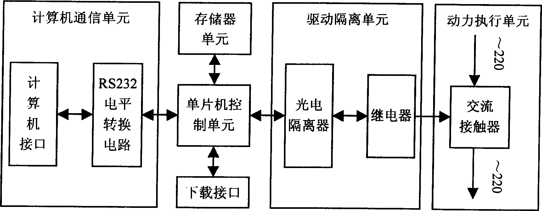
[0032] The structural block diagram of the switch machine controller in this example is shown in figure 2 . The switch machine controller in this example includes a single-chip microcomputer control unit, a memory unit, a drive isolation unit, and a power execution unit. The single-chip microcomputer control unit is composed of a single-chip microcomputer (89S52) as the core, the drive isolation unit includes a photoelectric isolator and a relay, and the power execution unit is an AC contactor. The single-chip microcomputer runs the program in the memory, outputs control instructions, drives the relay through the photoelectric isolator, and the relay drives the AC contactor to control the power supply of the power socket on the power load cabinet to realize the power switch control of the power equipment. According to the aging requirements of different power equipment, the control command can be a random power on and off control command to conduct random power on and off im...


PUM


Abstract

The invention relates to power supply technique, especially relating to power supply device ageing test, providing a power supply device ageing test method and device. And its technical solution: the method makes ON and OFF surge test on the power supply device in the ageing test course. And the ageing test device comprises distribution cabinet and power load cabinet, and switch controller, where the switch controller is connected with the power load cabinet to control the power supply of the power load cabinet. And it can detect abilities of components to resist ON surge current; and raise utilization ratio of the ageing test device and save production cost.

Description

technical field [0001] The invention relates to power supply technology, in particular to aging test of power supply equipment. Background technique [0002] In the power equipment test, through the high temperature full load aging test, the reliability of the power equipment is checked, and the early failure components are eliminated. The traditional aging test device includes a power distribution cabinet and a power load cabinet. During the test, the power supply equipment is connected to the power load unit in the power load cabinet, and the power distribution cabinet provides power for the power supply equipment. The power load unit generally uses a resistive load. According to the output voltage and output power of the power supply device, adjust the power load unit so that the power supply device is placed in a full-load working state. After the setting is completed, perform continuous high-temperature aging for several hours. Because high temperature aging needs to m...

Claims


Application Information

Patent Timeline
IPC IPC(8): G01R31/40G01R31/42
Inventor 陈京川丁时安黄凤江黄兴华唐燕春
Owner MAIPU COMM TECH CO LTD
Learn More