Left hand microstrip transmission line, and time delay line structured based on the transmission line

Inactive Publication Date: 2006-12-06
UNIV OF SCI & TECH OF CHINA
View PDF0 Cites 8 Cited by
  • Summary
  • Abstract
  • Description
  • Claims
  • Application Information

AI Technical Summary

Problems solved by technology

[0012] The technical purpose of the present invention: to propose a compact planar left-handed microstrip transmission line to overcome the disadvantages of the existing left-handed microstrip transmission line that are relatively large in area or volume and difficult to integrate; and based on this left-handed microstrip transmission line Construct a miniaturized time delay line to overcome the shortcomings of existing time delay lines such as large volume, large loss, and low efficiency

Method used


Image

  • Left hand microstrip transmission line, and time delay line structured based on the transmission line
  • Left hand microstrip transmission line, and time delay line structured based on the transmission line
  • Left hand microstrip transmission line, and time delay line structured based on the transmission line

Examples


Embodiment 1

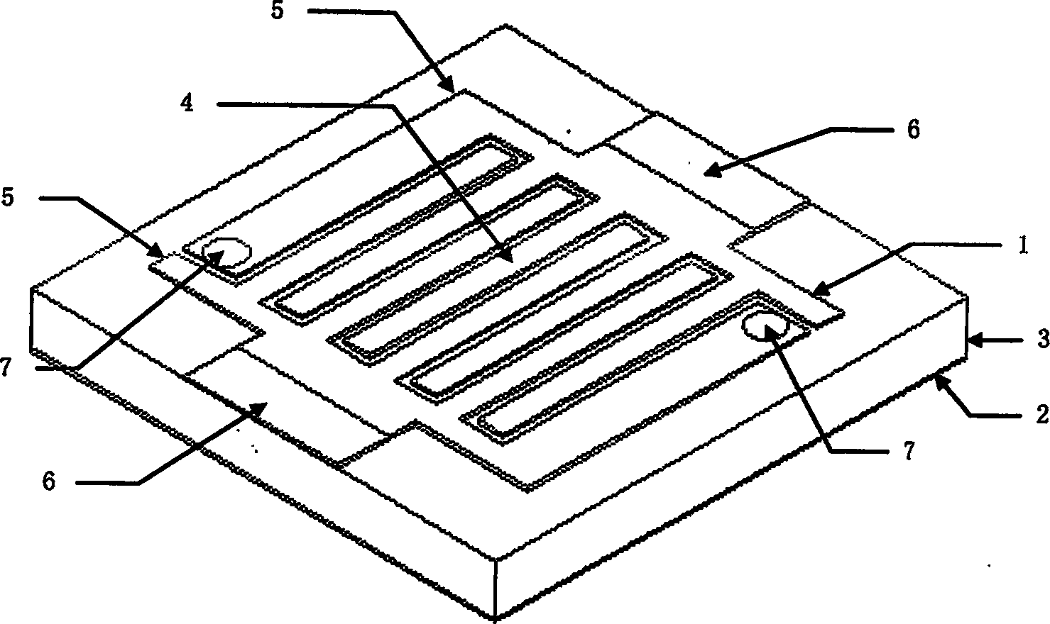
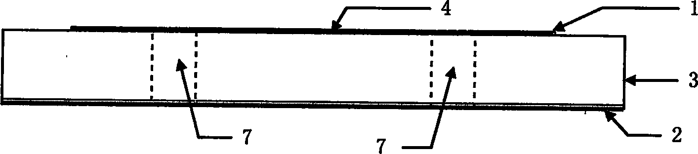
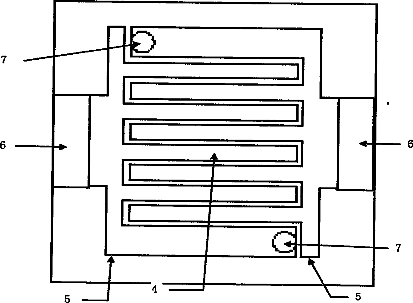
[0042] In this embodiment, the left-hand microstrip transmission line unit is made on a conventional printed circuit board. The printed circuit board is the most common dielectric coated conductor board. The upper surface layer 1 and the lower surface layer 2 are metal conductor copper, and the thickness is 0.004. mm, the ground of the left-hand transmission line is formed by the metal copper of the lower surface layer, and the middle layer 3 is a Rogers TMM 10i dielectric board with a dielectric constant of 9.8 and a thickness of 0.254 mm. The metal interdigital capacitor 4 is made by printed circuit technology on the upper surface layer. The number of interdigital pairs is 5 (that is, there are 5 interdigital fingers in each plane interdigital structure). Two plane interdigital structures are placed in cross and parallel, and the inner side is 4 The interdigital width is 0.1mm, the interdigital spacing is 0.1mm, and the interdigital length is 1mm; the outermost pair of interdigi...

Embodiment 2

[0045] In this embodiment, the left-hand microstrip transmission line unit is fabricated on a conventional printed circuit board. The upper surface layer 1 and the lower surface layer 2 of the printed circuit board are made of metal conductor copper with a thickness of 0.004mm. Forming the ground of the left-hand transmission line, the middle layer 3 is a Rogers RT / duroid5880 dielectric board with a dielectric constant of 2.2 and a thickness of 0.254mm. The metal interdigital capacitor 4 is made by printed circuit technology on the upper surface layer, the number of interdigital pairs is 3, two plane interdigital structures are placed in cross and parallel, the inner side 2 pairs of interdigital width are 0.1mm, the interdigital spacing is 0.1mm, interdigital Length 1mm; the outermost pair of interdigital width is 0.3mm, the interdigital spacing is 0.1mm, and the interdigital length is 1mm. The outer ends of each plane interdigital structure are connected by sidebands 5, with a si...

Embodiment 3

[0059] The time delay line based on the left-hand microstrip transmission line in this embodiment is also made on a printed circuit board. The upper surface layer 1 and the lower surface layer 2 of the printed circuit board are made of metal conductor copper with a thickness of 0.004mm. The metal copper forms the ground of the left-hand transmission line, and the middle layer 3 is a RogersRT / duroid 5880 dielectric board with a dielectric constant of 2.2 and a thickness of 0.254 mm. On the upper surface layer, a metal interdigital capacitor 4 is made by printed circuit technology, with 3 pairs of interdigital pairs, two interdigital structures are placed in cross and parallel, the interdigital width is 0.1mm, the interdigital distance is 0.1mm, and the interdigital length is 1.415mm. A sideband 5 is connected to the outer end of each interdigital structure with a side width of 0.1mm and a sideband length of 1.4mm. The feeders of the input and output ports 6 are respectively located...


PUM


Abstract

The left hand microstrip transmission line (MTL), and time delay line based on the said MTL are produced from medium covered conductor plate. Capacitance is formed by two frames of plane cross fingers structures produced on conductor layer on up surface of medium plate. Moreover, via hole is prepared on outer cross finger or side strip on each plane cross fingers structure. Conductors on via holes connect capacitances to ground so as to constitute inductance. Ports of inputting and outputting signals of MTL are located at side strips on two ends of cross fingers capacitance. On plane carrier, the left hand MTL realizes series capacity and shunt inductance directly with features of compact structure, easy of manufacture, small size, low loss, and capability of applicable to microstrip IC. The MTL possesses symmetric structure, multiple adjustable parameters so as to suit requirements by different performances and different applications easily.

Description

1. Technical Field: [0001] The invention belongs to the field of microwave technology, and relates to a transmission line structure and a time delay line designed by using the transmission line. 2. Background technology: [0002] Transmission lines and time delay lines are common devices in the field of microwave technology and are used in many applications, such as signal processing systems, radar systems, and phased antenna arrays. [0003] The left-hand transmission line is a new concept put forward in recent years. It has some excellent electromagnetic characteristics when using it for microwave transmission, which has attracted people's attention. The currently proposed left-handed transmission lines are mainly based on two structures of microstrip line and coaxial line, but the currently proposed left-handed transmission line structures generally have the disadvantages of large area or volume and not easy to integrate. [0004] In November 2005, Salhai et al. published a pa...

Claims


Application Information

Patent Timeline
Patent Type & Authority Applications(China)
IPC IPC(8): H01P3/08
Inventor 朱旗陈立均
Owner UNIV OF SCI & TECH OF CHINA
Why Eureka
Try Eureka