Electronic ballast in use for light tunable gas discharge lamp in high intensity
A gas discharge lamp and electronic ballast technology, applied in the field of power electronics, can solve the problems of large capacitance and inductance voltage stress, large capacitance and inductance loss, and high cost, and achieve high operating frequency, increase starting voltage, and low cost. Effect
- Summary
- Abstract
- Description
- Claims
- Application Information
AI Technical Summary
Problems solved by technology
Method used
Image
Examples
Embodiment Construction
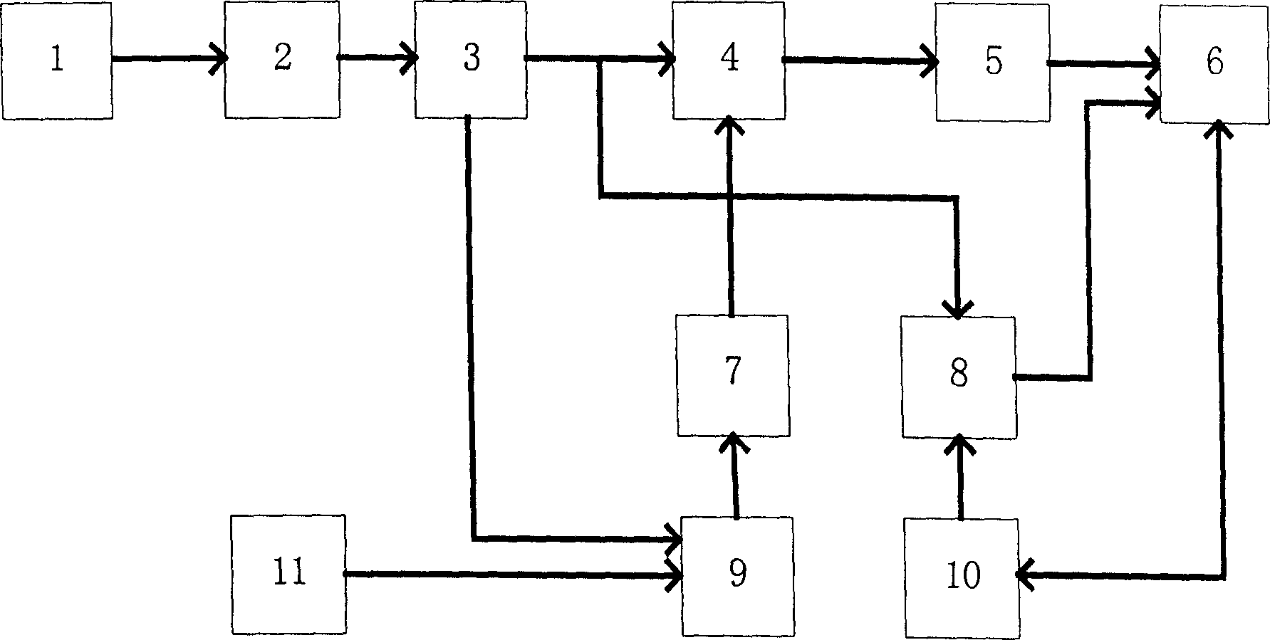
[0014] refer to figure 1 , the present invention mainly consists of a low-pass filter rectifier circuit 2, a power factor correction circuit 3, a bridge inverter circuit 4, a T-shaped filter resonant circuit 5, an isolation drive circuit 7, a start circuit 8, a frequency adjustment circuit 9, and a start control circuit 10 and dimming signal control circuit 11. Among them, the low-pass filter rectifier circuit 2, the power factor correction circuit 3, the bridge inverter circuit 4 and the T-type filter resonance circuit 5 are sequentially connected to form the main circuit of the electronic ballast, the isolation drive circuit 7, the start circuit 8, the frequency adjustment The circuit 9, the starting control circuit 10 and the dimming signal control circuit 11 form the control loop of the electronic ballast, and complete the control functions of starting control and frequency modulation and dimming. 1 is mains electricity.
[0015] The start circuit 8 and the start control...
PUM
 Abstract
Description
Claims
Application Information
 - R&D
- Intellectual Property
- Life Sciences
- Materials
- Tech Scout
- Unparalleled Data Quality
- Higher Quality Content
- 60% Fewer Hallucinations
Browse by: Latest US Patents, China's latest patents, Technical Efficacy Thesaurus, Application Domain, Technology Topic, Popular Technical Reports.
© 2025 PatSnap. All rights reserved.Legal|Privacy policy|Modern Slavery Act Transparency Statement|Sitemap|About US| Contact US: help@patsnap.com


