Electronic device for direct slurry atomization and deposition

A technology of atomization deposition and electronic slurry, which is applied in spraying devices, devices for coating liquid on the surface, circuits, etc., can solve the problems of high cost and complex equipment composition, achieve convenient operation, improve electrical performance, and be easy to replace Effect

Active Publication Date: 2006-12-13
HUAZHONG UNIV OF SCI & TECH
View PDF1 Cites 10 Cited by
  • Summary
  • Abstract
  • Description
  • Claims
  • Application Information

AI Technical Summary

Problems solved by technology

The biggest feature of this technology is that the characteristic line width is at the nanometer level, but the cost is high and the equipment is complex. It can only be applied industrially in some places that require extremely high processing precision.

Method used


Image

  • Electronic device for direct slurry atomization and deposition
  • Electronic device for direct slurry atomization and deposition
  • Electronic device for direct slurry atomization and deposition

Examples


Embodiment 1-3

[0038] Embodiment 1-3 is in ceramic (Al 2 o 3 , 96wt%) deposited direct-write high-temperature Ag conductor on the substrate. Among the two-fluid atomizing nozzles, the diameter of the gas nozzle is Φ0.22mm, the diameter of the liquid nozzle is Φ0.5mm, the diameter of the deposition nozzle is Φ0.4mm, and the viscosity of the slurry is 2Pa.S. Other parameters are shown in Table 1.

[0039] example

Embodiment 4-6

[0041] Examples 4-6 deposited direct-write Ag conductors on Si substrates. In the two-fluid atomizing nozzle, the diameter of the gas nozzle is Φ0.20mm, the diameter of the liquid nozzle is Φ0.50mm, the diameter of the deposition nozzle is Φ0.10mm, the viscosity of the slurry is 2Pa.S, and other parameters are shown in Table 2

[0042] example

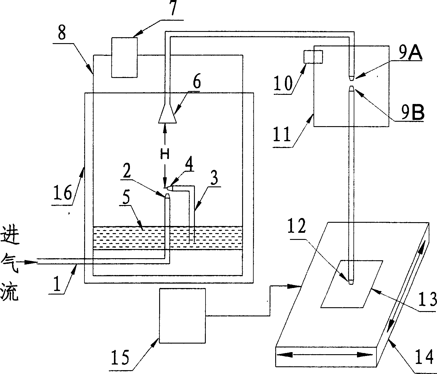
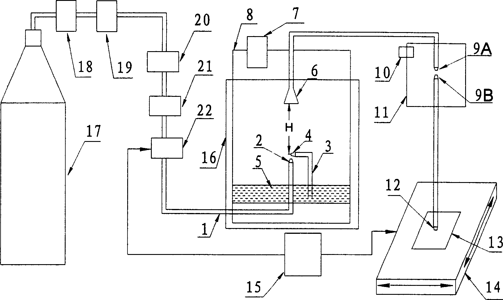
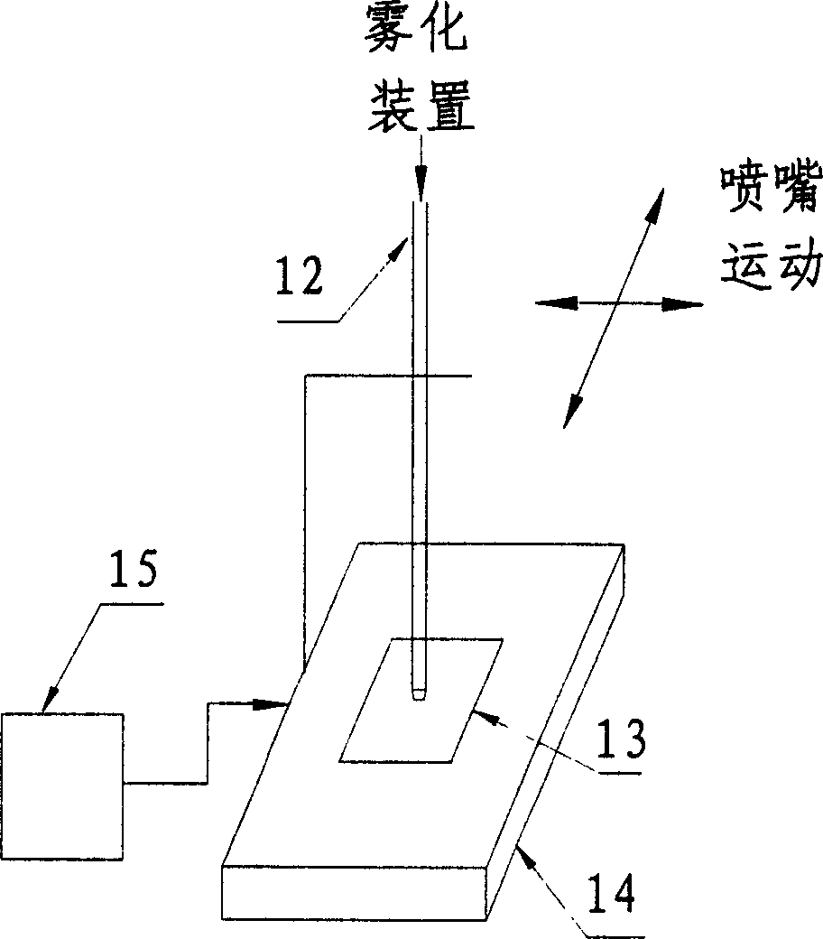
[0043] The electronic slurry direct writing technology proposed by the present invention uses the atomizing nozzle to atomize the electronic slurry into fine particles, and then transports the electronic slurry to the nozzle along the pipeline under the guidance of the air flow, and deposits it on the substrate through the nozzle to form a preset circuit graphics. Among them, the deposition path is controlled by the control command issued by the numerical control workbench. The electronic paste includes conductive paste, resistive paste, dielectric paste or other electronic paste. The substrate can be ceramic, glass, silicon,...


PUM


Abstract

The disclosed electronic slurry atomization deposition direct-write device comprises: a deposition nozzle, a base plate, a work bench controlled by a controller, two atomizing nozzles every with a gas nozzle connected to gas source and a liquid nozzle connected to slurry pipe end both in the atomization cavity, and a butt-joint jet pipe with co-axial upper and lower jet pipes, wherein arranging a micro-pressure gauge in the cavity, arranging a adjustable valve in the decompression recovery cavity. This invention has well atomization effect, and runs stably and conveniently.

Description

technical field [0001] The invention belongs to the technical field of electronic manufacturing, and in particular relates to an electronic slurry atomization deposition direct writing device, which can be applied to the manufacture of electronic components, including the manufacture of conductors, resistors, capacitors, inductors, sensors and electrodes. Background technique [0002] At present, with the development of electronic manufacturing technology in the direction of integration, miniaturization, short-term, small batch, multi-variety and three-dimensional manufacturing, the width and spacing of wires are required to be smaller and smaller, and multi-layer wiring can be realized. Traditional manufacturing processes, such as screen printing and low-resolution lithography, are difficult to meet the requirements of high-precision, small-batch and rapid manufacturing. It is easy to produce large errors in the manufacturing, resulting in a decrease in yield; the minimum l...

Claims


Application Information

Patent Timeline
Patent Type & Authority Applications(China)
IPC IPC(8): B05C5/02B05C11/10B05B13/02H05K3/10H01L49/02
Inventor 曾晓雁李祥友李敬李金洪王小宝
Owner HUAZHONG UNIV OF SCI & TECH
Why Eureka
Try Eureka