Packet transmitter apparatus

A packet sending and packet sending technology, which is applied in the field of packet sending devices, can solve the problems of not being able to use the Internet, heavy processing by the receiver, etc., and achieve the effect of realizing copyright protection, ensuring signal interchangeability, and ensuring privacy

Active Publication Date: 2007-01-10
PANASONIC CORP
View PDF1 Cites 7 Cited by
  • Summary
  • Abstract
  • Description
  • Claims
  • Application Information

AI Technical Summary

Problems solved by technology

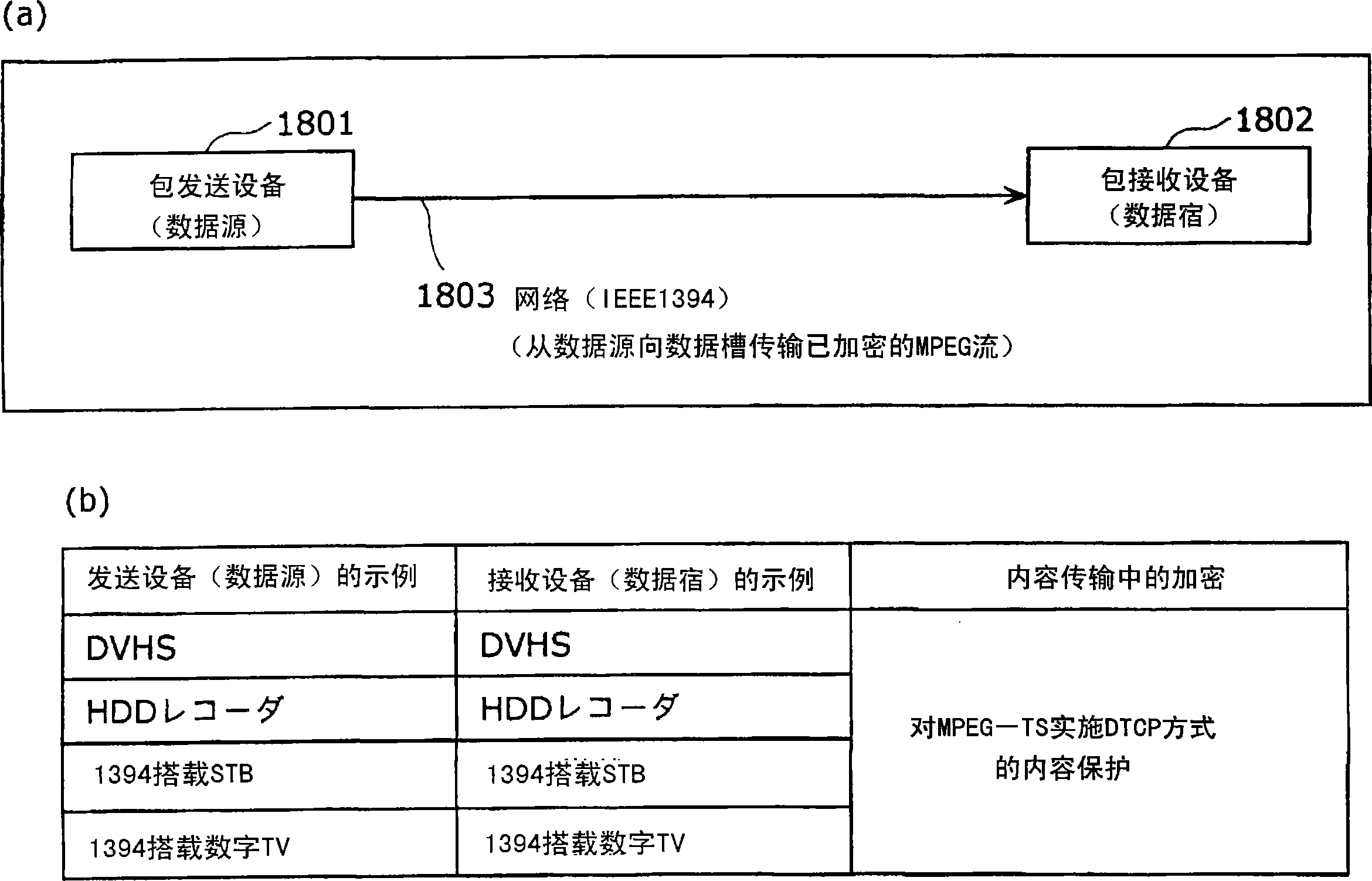
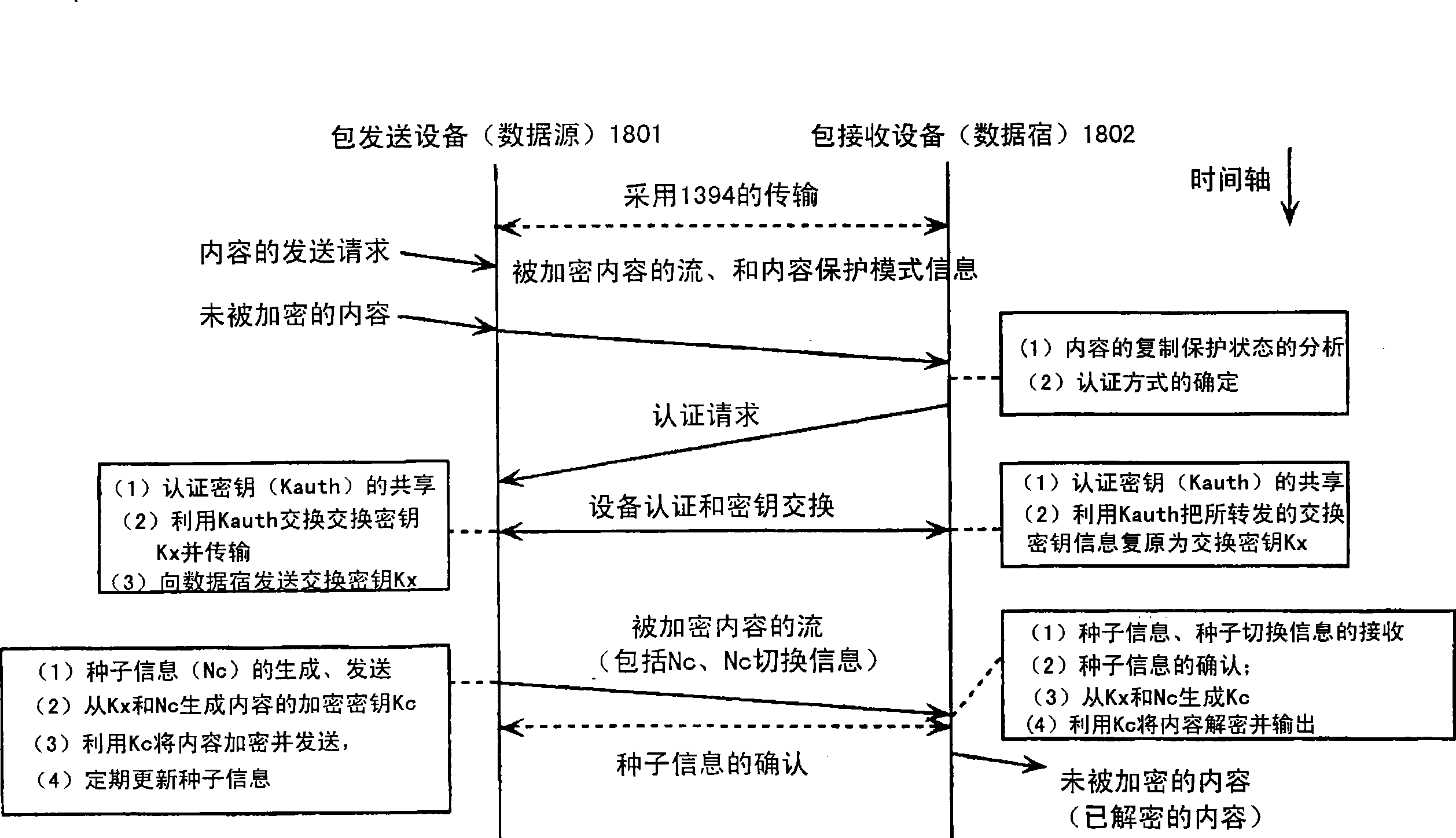
In the past DTCP method, in IEEE1394, although the real-time transmission of MPEG-TS signals can be realized by using synchronous packet transmission, there are the following major problems. The standard communication protocol of the Internet, that is, Internet Protocol (IP), cannot be used. (IEEE802.3), wireless LAN (IEEE802.11) and other networks that can transmit IP packets
[0012] That is, there is a big problem that content corresponding to digital copyright protection, such as terrestrial / BS digital broadcasting and server-based broadcasting, cannot be transmitted between a packet sending device and a packet receiving device logically connected by IP on the basis of copyright protection
[0013] In addition, in the transmission of live (live) playback, when using HTTP (HyperTextTransfer Protocol), whenever there is an HTTP request, it is necessary to calculate the header length and transmission content length attached to the encryption on the receiving side. to deal with heavier problems
[0014] In addition, there is a problem that it is difficult to simply implement special playback such as fast-forwarding, rewinding, and slow-motion of the content stored in the hard disk, etc.
[0015] In addition, there is a problem that it is difficult to simply use a common method to fast-forward, rewind, slow-play, etc. to play the contents of different storage formats stored in hard disks and optical discs, etc.

Method used


Image

  • Packet transmitter apparatus
  • Packet transmitter apparatus
  • Packet transmitter apparatus

Examples


Embodiment approach 1

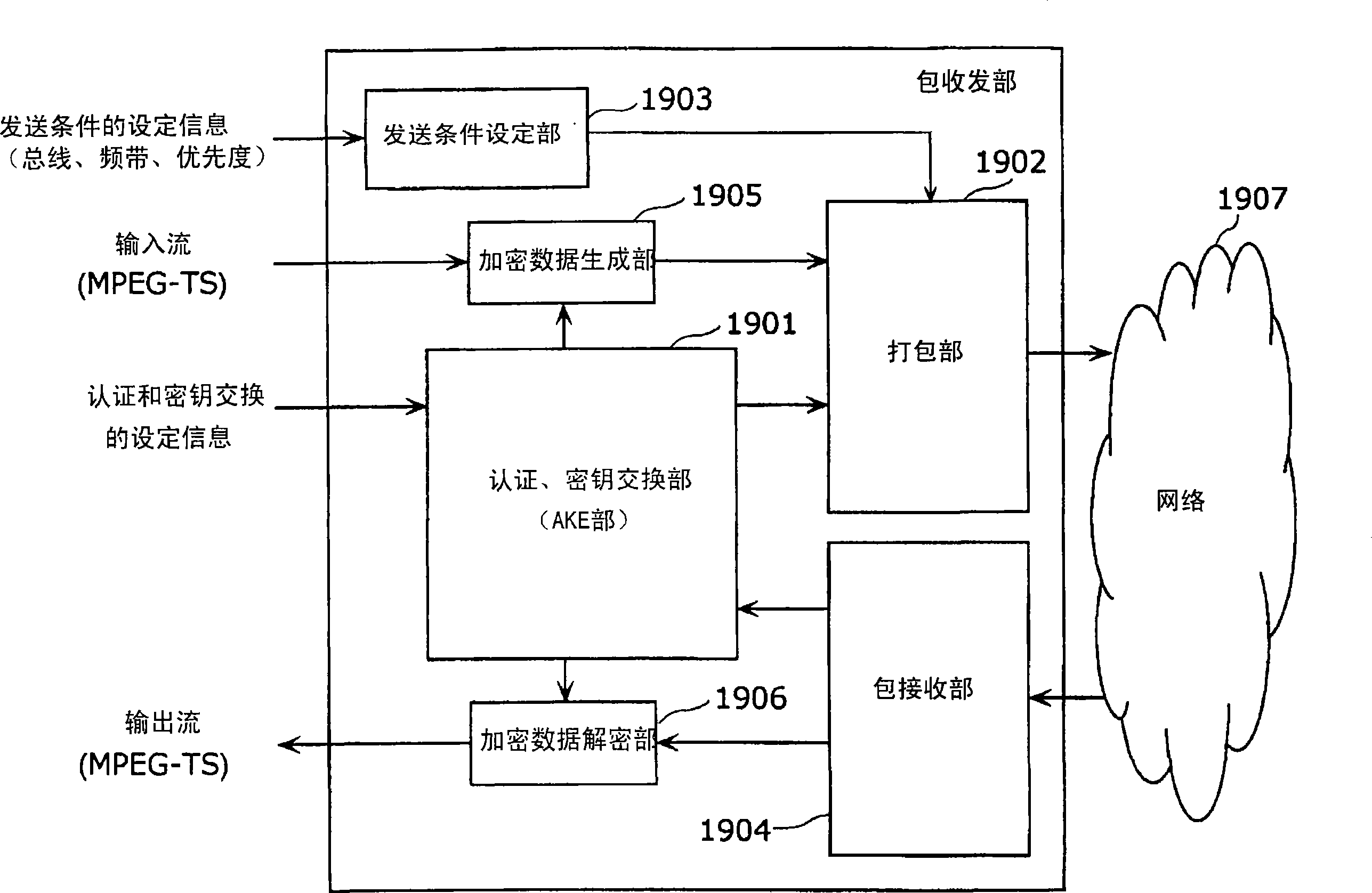
[0115] First, Embodiment 1 of the present invention will be described. Figure 9 It is a block diagram showing the structure of the packet transmission and reception unit 401 of this embodiment. The packet transceiver section 401 is shown simultaneously Figure 5The hypothetical functional units of the packet sending unit that the shown packet sending device 101 has and the packet receiving unit that the router 102 has may also be a functional block diagram showing a packet sending and receiving unit that has a packet sending and receiving function (this is true for all implementations below. The packet sending / receiving part in the method is the same.).

[0116] The packet transmission and reception unit 401 is a device that performs encrypted packet transmission and reception using AKE, and includes an AKE unit 402, a packaging unit 403, a transmission condition setting management unit 404, a packet transmission and reception unit 405, an encrypted data generation unit 406,...

Embodiment approach 2

[0137] Next, Embodiment 2 of the present invention will be described. Figure 11 It is a block diagram showing the structure of the packet transmission and reception unit 401a of this embodiment. exist Figure 11 In addition to the authentication mode determination part 601, other structures and Figure 9 The illustrated packet transceiver unit 401 is the same. Therefore, the new contents section is explained below.

[0138] exist Figure 11 In the AKE unit 402, as AKE setting information, the TCP port number for authentication is input as management control data shown in the figure to the transmission condition setting management unit 404. Here, the TCP port information for authentication is provided by a URI specifying an access location for each content or each playback channel, or URI information expanded by Query. At this time, regarding the URI, the URI information of the content is mapped to the main data part, and the authentication information of the content is m...

Embodiment approach 3

[0144] Next, Embodiment 3 of the present invention will be described. Figure 12 It is a block diagram showing the structure of the packet transmission and reception unit 401b of this embodiment. exist Figure 12 In addition to the input source information (playback, storage) of the AV data input to the transmission condition setting management unit 404, other configurations and Figure 11 The packet transmission / reception unit 401a of Embodiment 2 shown is the same. Therefore, the new contents section is explained below.

[0145] The transmission condition setting management unit 404 extracts necessary data for the input source information (playback, storage) of the input AV data, and outputs the data to the encrypted data generation unit 406 . Then, the encrypted information header adding unit 412 in the encrypted data generating unit 406 adds the necessary data transmitted from the transmission condition setting management unit 404 as an encrypted information head...


PUM


Abstract

A packet transmitter apparatus capable of transmitting, by use of widely utilized packets such as IP packets and the like, contents protected by content protection technologies such as DTCP and the like. There are included a transmission condition setting/managing part(404) for extracting, from received non-A/V data or A/V data, at least one of A/V data billing information, reproduction control information and copy control information and for producing, from the extracted information, encryption mode information indicative of an encryption mode that is a condition when A/V data are transmitted; an encrypted data producing part(406) for producing encrypted data by encrypting, based on a transmission condition as decided by a combination of input terminal information, data format information and attribute information, the received A/V data and further by adding, to the encrypted A/V data, an encryption information header based on the encryption mode information; and a packetizing part(403) for producing a packet by adding a packet header to the produced encrypted data.

Description

technical field [0001] The present invention relates to a packet transmission device that performs IP packetization of encrypted AV streams and transmits them with high quality using Ethernet (registered trademark) (wired LAN) such as IEEE802.3 and wireless LAN such as IEEE802.11. Background technique [0002] With the development of communication technology in recent years, various techniques for efficiently transmitting packets have been proposed (for example, refer to Patent Document 1). As one of them, conventionally, in general households, a digital playback tuner (tuner) and a DVHS video recorder are connected through an IEEE 1394 digital interface in a room, and MPEG-TS (Moving Picture Experts Group / Transport Stream) signal transmission. Wherein, when content protection such as Copy One Generation is applied to the playback content, in order to protect the content from being illegally copied, the content is encrypted and transmitted. A DTCP (Digital Transmission Co...

Claims


Application Information

Patent Timeline
Patent Type & Authority Applications(China)
IPC IPC(8): H04L12/56H04L12/721
Inventor 森冈芳宏绫木靖臼木直司
Owner PANASONIC CORP
Why Eureka
Try Eureka