Variable valve lift device of internal combustion engine

A technology of valve lift and internal combustion engine, which is applied to valve devices, mechanical equipment, engine components, etc., to achieve the effect of easy assembly, avoiding large-scale, and realizing compactness

Inactive Publication Date: 2007-01-24
HONDA MOTOR CO LTD
View PDF2 Cites 13 Cited by
  • Summary
  • Abstract
  • Description
  • Claims
  • Application Information

AI Technical Summary

Problems solved by technology

In order to increase the torsional rigidity, it is conceivable to integrally form the movable support shaft and the crank arm by forging, etc., but if the second link arm is to be assembled to the crank member in which the movable support shaft and the crank arm are integrated, it is necessary to use The connecting hole provided in the second link arm for inserting the movable support shaft has a two-part structure like a large end portion of a connecting rod, so that the enlargement of the second link arm cannot be avoided.

Method used


Image

  • Variable valve lift device of internal combustion engine
  • Variable valve lift device of internal combustion engine
  • Variable valve lift device of internal combustion engine

Examples


Embodiment 1

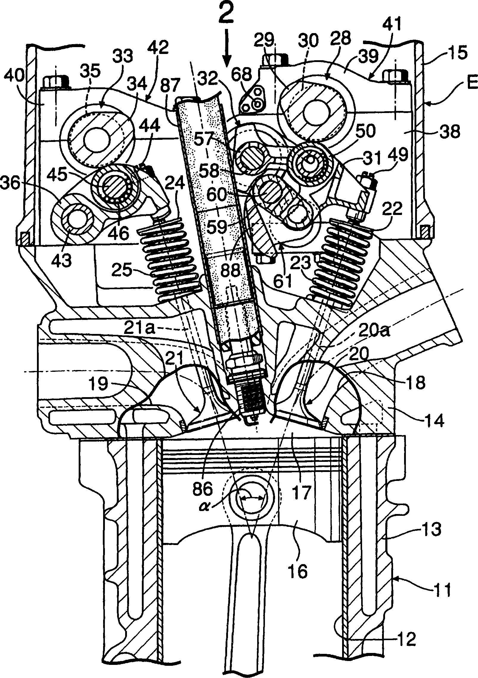
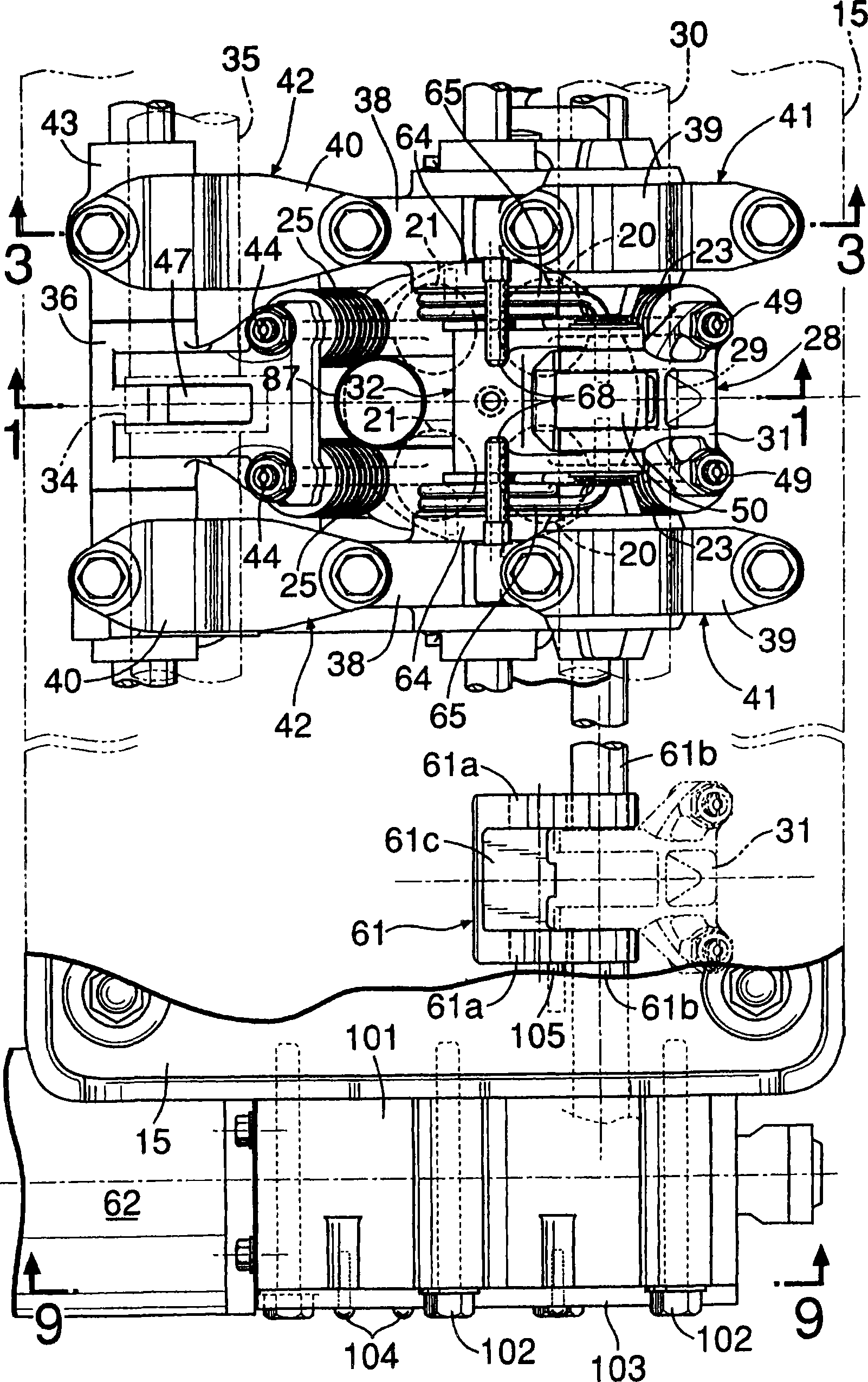
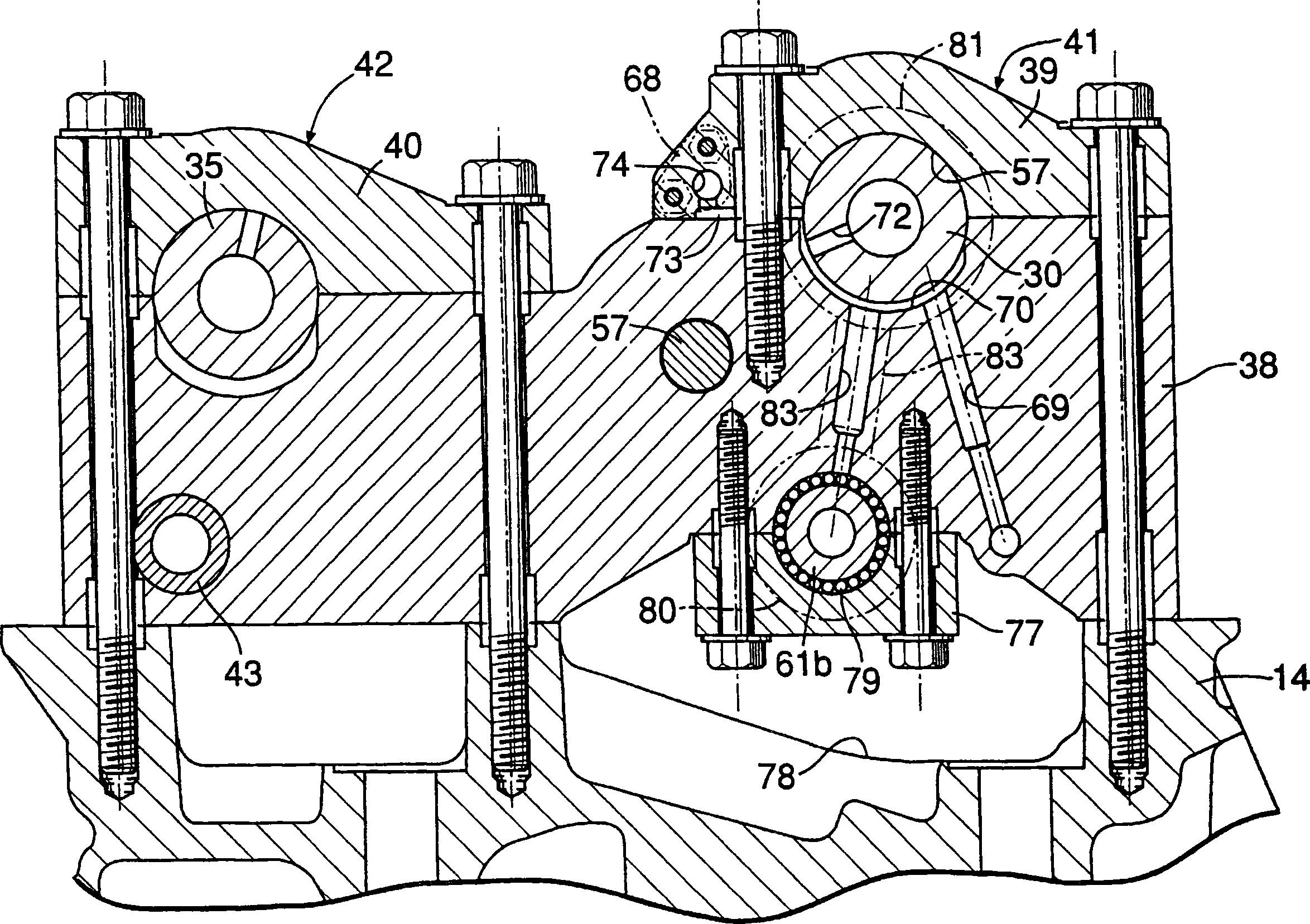
[0046] Figure 1 to Figure 10 shows an embodiment of the present invention.

[0047] first in figure 1 Among them, the internal combustion engine main body 11 of the internal combustion engine E as an in-line multi-cylinder internal combustion engine includes: a cylinder block 13 with a cylinder bore 12 (cylinder bore) ... inside; a cylinder head 14 joined to the top surface of the cylinder block 13; The cylinder head cover 15 on the top surface of the cylinder bore 12 ... is slidably fitted with a piston 16 ..., and the combustion chamber 17 ... opposite to the top of each piston 16 ... is formed between the cylinder block 13 and the cylinder head 14 .

[0048] The cylinder head 14 is provided with an intake port 18 ... and an exhaust port 19 ... that can communicate with each combustion chamber 17 ..., and each intake port 18 ... is opened and closed by a pair of intake valves 20 ... as internal combustion engine valves. , Each exhaust port 19... is opened and closed by a...


PUM


Abstract

A variable valve lift device of an internal combustion engine, wherein a first link rocker arm (58) rotatably pivoted at the fixed position of an engine body is rotatably connected to a rocker arm (31). A movable pivot shaft (60) rotatably pivoting the other end part of a second link arm (59) having one end part rotatably connected to the rocker arm (31) comprises crank webs (61a) holding the second link arm (59) from both sides and connection parts (61c) integrally connecting both crank webs (61a) to each other at positions where the interference thereof with the second link arm (59) can be avoided, and is connected to a crank member (61) formed in a crank shape so that the crank member (61) can be drivingly rotated by a drive means. Thus, the lift amount of an engine valve can be steplessly varied, the torsional rigidity of the crank member can be secured while securing the assembling workability of the second link arm to the crank member, and the size of the device can be reduced.

Description

technical field [0001] The present invention relates to a valve lift variable device of an internal combustion engine, which continuously changes the lift amount of an internal combustion engine valve serving as an intake valve or an exhaust valve. Background technique [0002] In order to continuously change the lift of the internal combustion engine valve, Patent Document 1 discloses such a valve train: a valve abutting portion is provided on one end side of the rocker arm to abut against the internal combustion engine valve, and on the other end of the rocker arm One end of a push rod is fitted to one end, and a link mechanism is provided between the other end of the push rod and the valve driving cam. [0003] However, in the valve train disclosed in Patent Document 1, it is necessary to ensure a large space between the valve train cam and the rocker arm for arranging the link mechanism and the push rod, which increases the size of the valve train. And because the drivi...

Claims


Application Information

Patent Timeline
Patent Type & Authority Applications(China)
IPC IPC(8): F01L13/00
Inventor 藤井德明米川明之藤本智也中村胜则吉田惠子
Owner HONDA MOTOR CO LTD
Why Eureka
Try Eureka