Bistroke ignition type combustible particle internal combustion engine

A particulate, combustion technology, used in internal combustion piston engines, combustion engines, fuel systems, etc.

Inactive Publication Date: 2007-01-31
成都安捷网际服务有限公司
View PDF0 Cites 2 Cited by
  • Summary
  • Abstract
  • Description
  • Claims
  • Application Information

AI Technical Summary

Problems solved by technology

thereby solving the problem of ensuring ignition of combustible particulate fuel

Method used


Image

  • Bistroke ignition type combustible particle internal combustion engine

Examples


Embodiment Construction

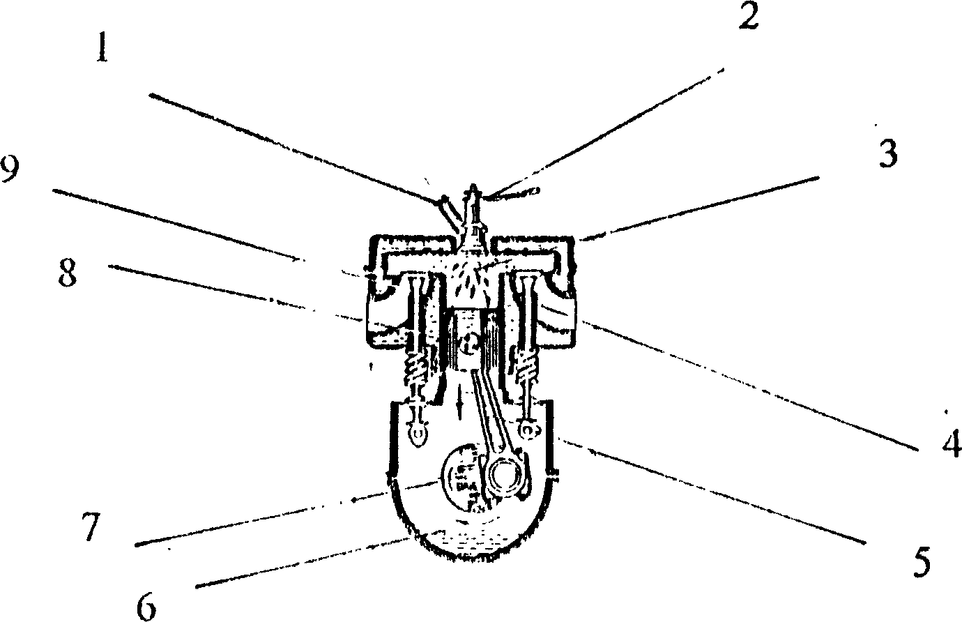
[0007] When the internal combustion engine is working, the piston 8 moves from the bottom dead center to the upward dead center, the exhaust valve 4 is opened, and the combustion exhaust gas is discharged through the exhaust valve through the exhaust pipe; the piston 8 moves from the top dead center to the downward dead point, and the intake valve 9 is opened , the cylinder 3 starts to intake air, and when the piston 8 moves a certain distance, the intake valve 9 closes, and at the same time, the fuel nozzle 2 ejects combustible particulate fuel at high pressure, and the flame of the ignition chamber 1 enters the cylinder 3 through the flame port of the ignition chamber, and ignites the combustible particulate fuel Fuel pushes the piston 8 down to do work. At this point, a working cycle is completed.

[0008] Two-stroke ignitable combustible particle internal combustion engine, because the main component of its fuel is renewable substances, it can be used in the internal combu...


PUM


Abstract

The invention uses combustible particles as a main fuel and adopts priming ignition, i.e. sets an ignition chamber to ensure the ignition of the combustible particle fuel. One operating cycle of the inventive internal combustion engine finishes by two strokes, the exhaust stroke and the work stroke. The piston during the work stroke can move from the top dead center to the bottom dead center in order of four process of suction, jetting the fuel, ignition and combustion. The invention consists of an ignition chamber, a fuel nozzle, a cylinder, an exhaust valve, a connecting-rod, a crankshaft, a crankcase, a piston and an air intake valve.

Description

technical field [0001] The invention relates to the field of power equipment, especially used as power equipment on mobile tools (automobiles). Background technique [0002] Now the power equipment (engine) on the car uses fuel oil (diesel, gasoline) or gas (natural gas) as fuel. Since these fuels are non-renewable energy sources, it is necessary to improve the engine and use new alternative energy sources. The two-stroke ignition combustible particle internal combustion engine is a power device that uses combustible substances after particles (organic straw, hay) as the main fuel, and adopts the principle of ignition to ignite to provide power for mobile tools. Contents of the invention [0003] The technical solution adopted by the present invention to solve its technical problems is: [0004] 1 Pilot ignition, that is, an ignition chamber is set. The ignition process is to ignite the gas with the spark generated by the spark plug in the ignition chamber first, and the...

Claims


Application Information

Patent Timeline
Patent Type & Authority Applications(China)
IPC IPC(8): F02B19/00F02B45/02
CPCY02T10/125Y02T10/34Y02T10/12Y02T10/30
Inventor 李良正
Owner 成都安捷网际服务有限公司
Why Eureka
Try Eureka