
Semiconductor laser equipment

A laser device and semiconductor technology, applied in the direction of semiconductor laser devices, semiconductor lasers, laser devices, etc., can solve problems such as flow path blockage, achieve the effects of preventing corrosion, avoiding static sparks, and stabilizing laser output

Inactive Publication Date: 2007-01-31
HAMAMATSU PHOTONICS KK
View PDF2 Cites 10 Cited by
  • Summary
  • Abstract
  • Description
  • Claims
  • Application Information

AI Technical Summary

Problems solved by technology

When the above-mentioned corrosion continues, the possibility of short circuit due to blockage of the flow path, water leakage, electric leakage, etc. will increase.

Method used


Image

  • Semiconductor laser equipment
  • Semiconductor laser equipment
  • Semiconductor laser equipment

Examples


Embodiment Construction

[0033] Next, we use Figure 1 to Figure 10 Each embodiment of the semiconductor laser device according to the present invention will be described in detail. In addition, in the description of the drawings, the same reference numerals are attached to the same parts and places, and repeated descriptions are omitted.

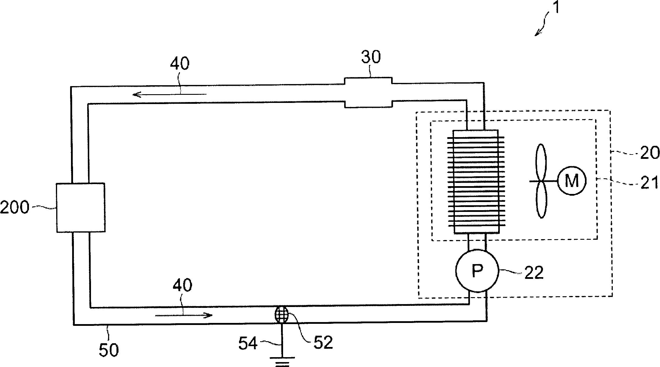
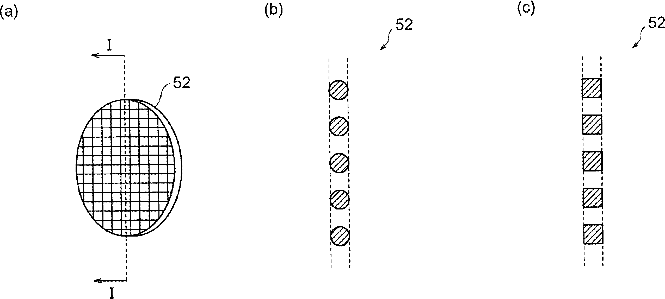
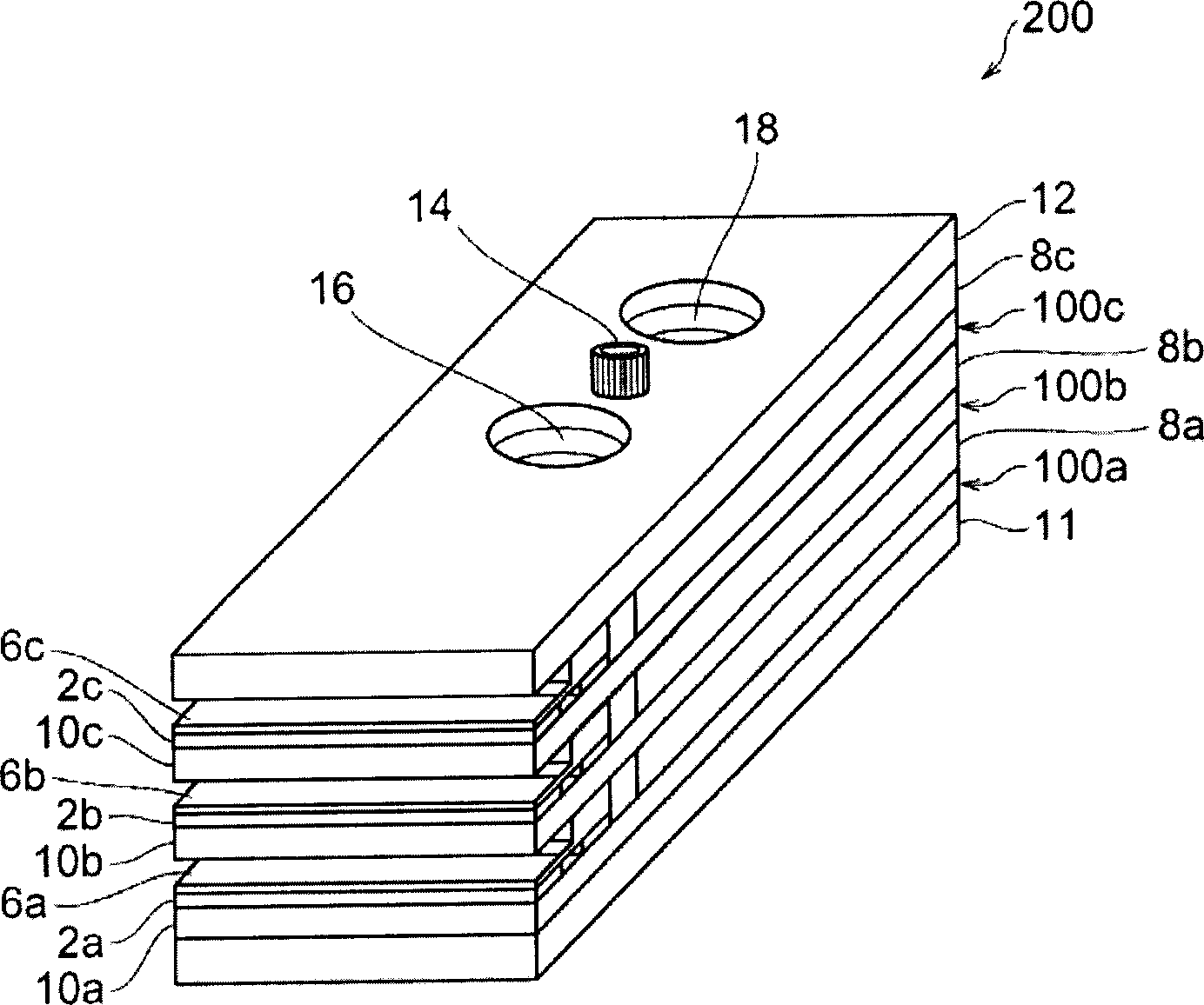
[0034] figure 1 It is a diagram showing the configuration of the first embodiment of the semiconductor laser device according to the present invention. Such as figure 1 As shown, the semiconductor laser device 1 according to the first embodiment includes a semiconductor laser stack 200, a cooler (refrigerant supplier) 20, an insulating pipe 50 connecting them, and a refrigerant 40 flowing through them.

[0035] The cooler 20 includes an air cooling unit 21 and a circulation pump 22 . The air cooling unit 21 cools the refrigerant, and the circulation pump 22 supplies the refrigerant 40 to the semiconductor laser stack 200 through the insulating pipe 50 .

[003...


PUM


Abstract

This invention relates to a semiconductor laser apparatus having a structure to prevent corrosion in a refrigerant flow path of a heat sink and cool stably a semiconductor laser array over a long period. The semiconductor laser apparatus has a semiconductor laser stack, a refrigerant supplier, an insulating piping, and a refrigerant. The refrigerant supplier supplies the refrigerant to the semiconductor laser stack. The refrigerant is comprised of fluorocarbon. The insulating piping is an insulating piping with flexibility. An grounded conductive material is arranged inside the insulating piping. The conductive material operates to remove static electricity generated where the refrigerant flows inside the insulating piping.

Description

technical field [0001] The present invention relates to a semiconductor laser device, which has a semiconductor laser array (Semiconductor Laser Array) as a light source, and also has a structure for effectively cooling the semiconductor laser array. Background technique [0002] In recent years, semiconductor laser devices capable of obtaining a high output of several W to 100 W have been developed. Such semiconductor laser devices are also used as light sources for laser scalpels, laser soldering irons, laser pointers, and the like. [0003] The electrical-optical conversion efficiency of the semiconductor laser array is about 50%, so half of the input power is turned into heat. Due to heat, laser output, efficiency, and component life are greatly affected. In order to efficiently cool the above-mentioned heat, a radiator using water, which has a high heat transfer efficiency and a large heat capacity, is used as a refrigerant. As the above-mentioned heat sink, for exam...

Claims


Application Information

Patent Timeline
Patent Type & Authority Applications(China)
IPC IPC(8): H01S5/024H01L23/473H01S5/40
CPCH01L2924/0002H01L23/473H01S5/405H01S5/02407H01S5/024H01L2924/00
Inventor 宫岛博文菅博文
Owner HAMAMATSU PHOTONICS KK
Learn More