

Surface sheet winding shaping method of composite material
A composite material, winding forming technology, applied in the direction of program control, instrumentation, electrical digital data processing, etc., can solve problems such as overhead or sliding wire, the performance of winding products and the negative impact of winding quality.
- Summary
- Abstract
- Description
- Claims
- Application Information
AI Technical Summary
Problems solved by technology
Method used
Image

Examples
specific Embodiment approach 1
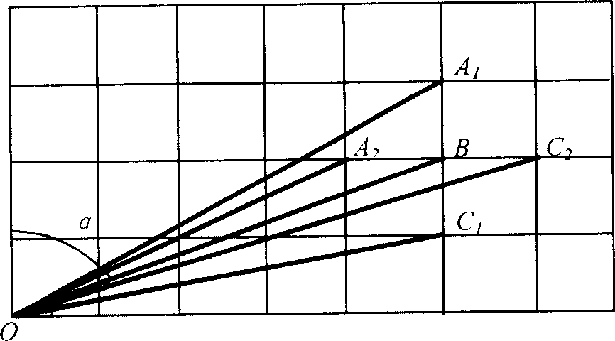
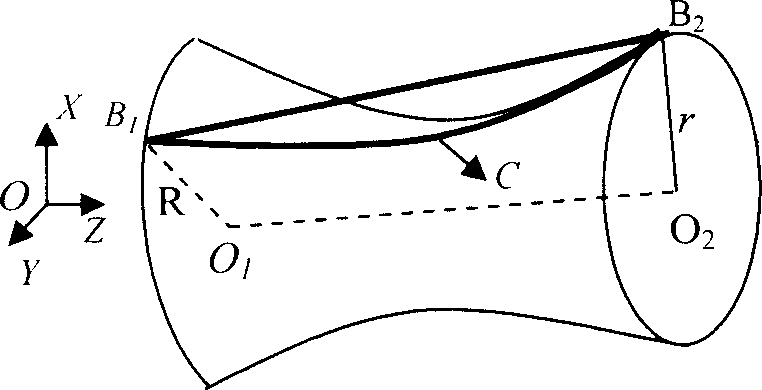
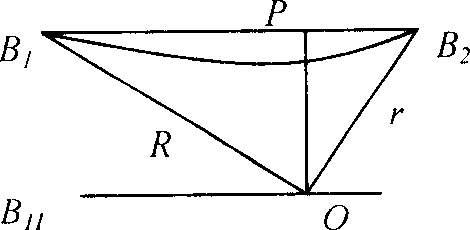
[0031] Specific implementation mode one: (refer to Figure 1 to Figure 6 ) This embodiment is implemented according to the following steps: firstly, determine the positions where the fiber voids exist on the mandrel, establish a data model of the mandrel, obtain detailed information on its surface, and perform detection and optimization control on the existing mandrel points. During the winding process, the hollow surface of the mandrel is prone to the phenomenon that the fibers are detached from the surface of the mandrel, such as figure 2 shown, where O 1 o 2 is the main axis of the mandrel, B 1 B2 is the overhead fiber, B 1 CB 2 is overhead fiber B 1 B 2 The projection on the mandrel, R and r are respectively B 1 and B 2 Mandrel radius at two points. Pick figure 2 The projection of each line on the XOY plane is image 3 In the case of , the straight line B 1 B 2 in curve B 1 B 2 The above illustrates the fiber and mandrel surface profile curve B 1 CB 2 Ther...
specific Embodiment approach 2
[0060] Specific implementation mode two: (see Figure 7 ) This embodiment is the winding of the air intake of the aircraft: first set up the data mandrel, apply CAD to build the data mandrel, and output the mandrel data file with the IEGES format; and carry out grid division to the data mandrel, set up the grid The shape of the element, the layout of the grid node position and the size of the tiny unit, the coordinates of these nodes are suffixed and output as a file in LIS format. Then, for the winding forming of the mandrel, the winding software is compiled according to the sheet winding theory, as shown in Figure 7: Calculation of stable trajectory: select a series of grid nodes that make the fibers stably wound, and determine the line shape of the winding trajectory. Simulation of winding line type: simulate the winding process in the form of 3D animation to verify the rationality of line type. Post-processing and winding data output: Select the constraint equation of the...
specific Embodiment approach 3
[0061] Specific implementation mode three: (see Figure 6 , Figure 7 ) This embodiment is winding with equal outstretched arm length: according to the movement stroke of each axis of the winding machine and the shape and size of the mandrel of the air inlet of the aircraft engine, on the premise of ensuring a sufficient winding range of motion and no collision interference, determine a line parallel to The straight line of the rotary spindle of the winding machine is used as the trajectory of the wire nozzle. When the mandrel rotates, the tangent line of the fiber on the mandrel intersects with the trajectory of the yarn nozzle, so as to obtain the yarn outlet point of the yarn nozzle. Figure 6 That is, the test situation when the design winding angle is 70°. The advantage of this solution is that only the main shaft, trolley and swing head are three-axis linkage winding, the movement is relatively simple and easy to control; there will be no collision between the wire noz...
PUM
 Abstract
Description
Claims
Application Information