Surface discharge shadow mask type plasma display panel

A technology of surface discharge and plasma, applied in the direction of solid cathode components, cold cathode tubes, etc., can solve the problems of low yield and high production cost of plasma display panel barriers, and achieve low cost, high luminous efficiency, and simple production process Effect

Inactive Publication Date: 2007-02-14
NANJING HUAXIAN HIGH TECH CO LTD
View PDF0 Cites 8 Cited by
  • Summary
  • Abstract
  • Description
  • Claims
  • Application Information

AI Technical Summary

Problems solved by technology

[0004] The object of the present invention is to solve the problem of the existing shadow mask type plasma display panel adopting the opposite discharge and the problem of high manufacturing cost and low yield of the barrier wall of the surface discharge type plasma display panel, and to invent a high-brightness, High luminous efficiency and low power consumption, easy-to-manufacture surface discharge type shadow mask plasma display panel

Method used


Image

  • Surface discharge shadow mask type plasma display panel
  • Surface discharge shadow mask type plasma display panel
  • Surface discharge shadow mask type plasma display panel

Examples


Embodiment 1

[0024] Such as Figure 1-5 shown

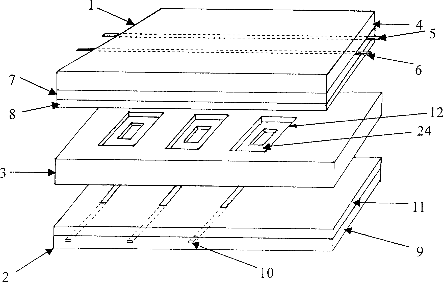
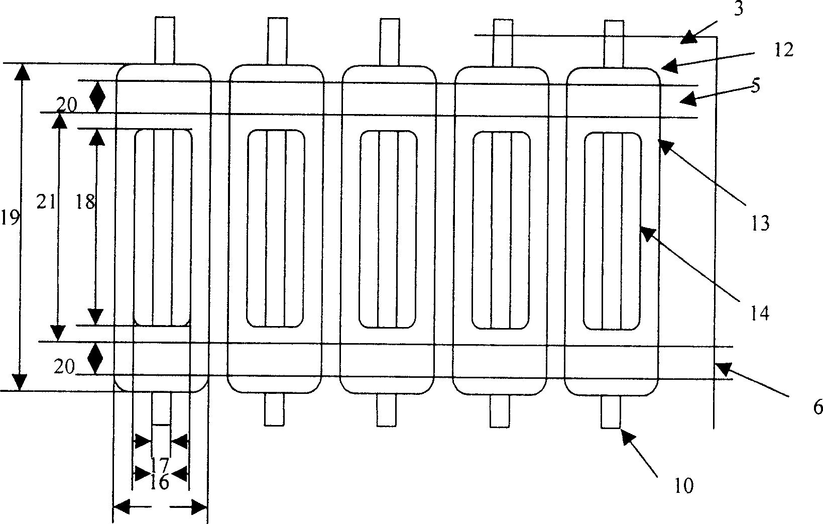
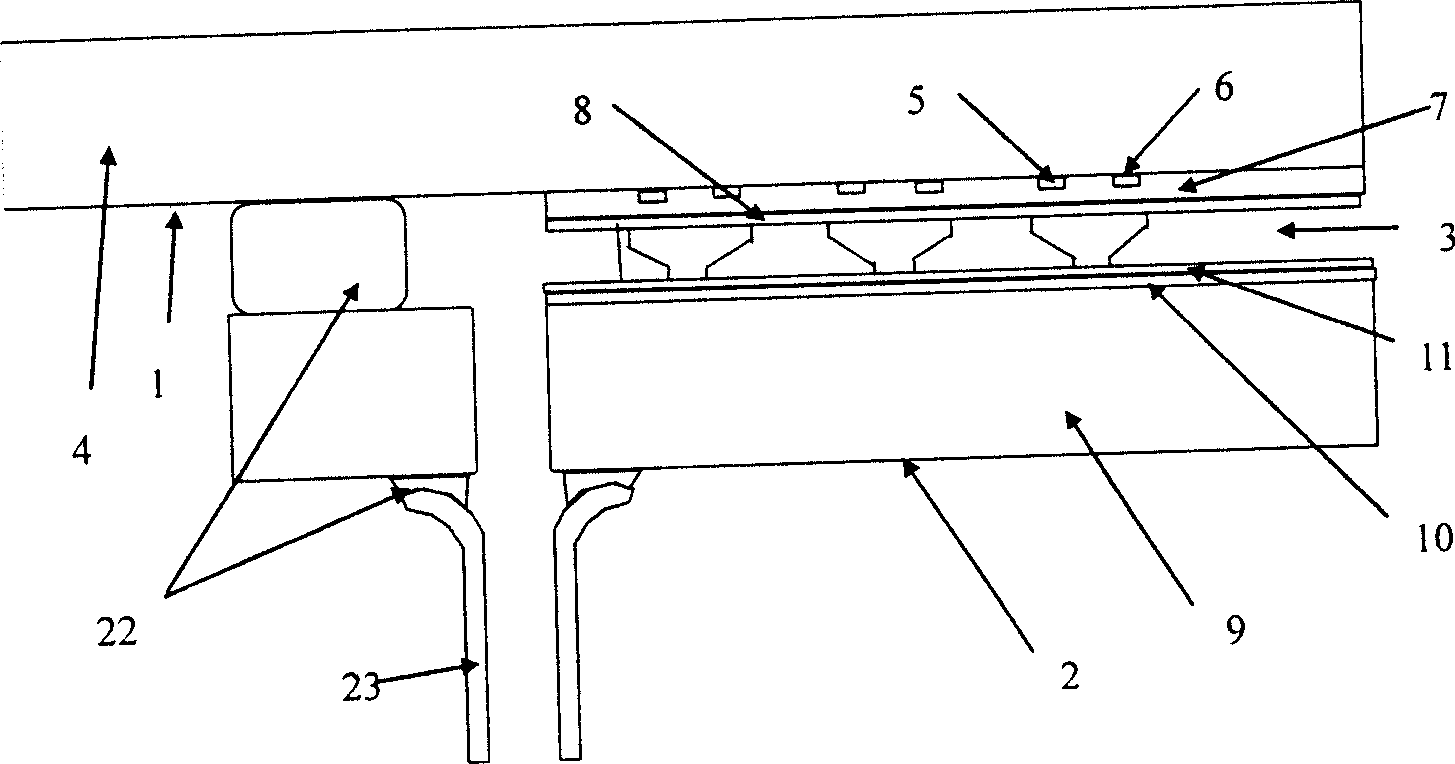
[0025] A surface discharge type shadow mask type plasma display panel, such as figure 1 As shown, it includes a front substrate 1 , a rear substrate 2 , and a shadow mask 3 , wherein the shadow mask 3 is located between the front and rear substrates 1 and 2 . The front substrate 1 is mainly composed of a front substrate glass substrate 4, first electrode pairs 5, 6, a dielectric layer 7, and a protective film 8, wherein the first electrode pairs 5, 6 are arranged in parallel and located on the front substrate glass substrate 4 On the top, it is only composed of Al or Ag electrodes, and there is no electrode composed of transparent conductive film (ITO). The electrode 5 is called a scan electrode, and the electrode 6 is called a sustain electrode. The dielectric layer 7 covers the first electrode pair 5, 6 to protect The membrane 8 covers the dielectric layer 7 . The rear substrate 2 is mainly composed of a rear substrate glass substrate 9,...

Embodiment 2

[0030] In the above-mentioned first embodiment, the shadow mask grid holes 12 form upper openings of any polygonal structure such as elongated, quadrilateral, circular, trapezoidal, hexagonal or octagonal, and the lower openings are elongated, and meet the requirements of the upper and lower openings. The condition that the center of the opening is on a straight line perpendicular to the mask surface. Such as Figure 4 , which constitutes the second embodiment group of the present invention, and the working principle is the same as that of the first embodiment.

Embodiment 3

[0032] In the above-mentioned first and second embodiments, the monochrome phosphor powder 24 is coated on the inner wall of the shadow mask grid hole 12 and the array formed by the surface part of the dielectric layer 11 of the rear substrate 2 corresponding to the lower opening 14, and is filled with a suitable Working gas, so that it produces ultraviolet light of corresponding wavelength to excite the ultraviolet phosphor to emit monochromatic visible light, thereby realizing image display, which constitutes the third embodiment group of the present invention, that is, monochromatic surface type shadow mask plasma display plate.


PUM


Abstract

This invention discloses a surface-discharged shadow mask plasma display panel including front and back base plates and a conductive shadow mask between and supporting them and containing a lattice hole array, in which, a pair of scan electrode and a sustain electrode at the front base plate, an addressing electrode and the lattice holes of the mask at the back base plate form a discharge unit applying the surface discharge mode, fluorescence powder is not only coated on the inside wall of the shadow mask lattice holes, but also coated at the position of the discharge unit at the back base plate to constitute a fluorescent powder area much larger than that of the shadow mask opposite-type discharge unit to increase the brightness and efficiency of irradiancy.

Description

technical field [0001] The present invention relates to a plasma display panel, in particular to a shadow mask type plasma display panel, in particular to a surface discharge type shadow mask type plasma display panel. Background technique [0002] The currently used shadow mask type plasma display panel mainly includes a front substrate, a rear substrate and a shadow mask. Starting from the glass substrate, the front substrate is the scanning electrode, the dielectric layer, and the protective layer formed on the surface of the dielectric layer; the rear substrate is starting from the glass substrate, and is the addressing electrode perpendicular to the scanning electrode, the dielectric layer, and the protective layer formed on the dielectric layer. The protective layer; the shadow mask sandwiched between the front and rear substrates is a thin metal mesh plate containing a mesh array processed from conductive materials (such as iron or its alloys). The above-mentioned fr...

Claims


Application Information

Patent Timeline
Patent Type & Authority Applications(China)
IPC IPC(8): H01J17/49H01J17/04
Inventor 李青张雄樊兆雯朱立锋王保平
Owner NANJING HUAXIAN HIGH TECH CO LTD
Why Eureka
Try Eureka