No wall flow technique and equipment for hydrogenation reaction chamber

A hydrogenation reactor and reactor technology, applied in the direction of chemical instruments and methods, chemical/physical processes, etc., to achieve the effects of good sealing performance, simple structure, and convenient installation

Active Publication Date: 2007-02-21
中国寰球工程有限公司辽宁分公司
View PDF0 Cites 7 Cited by
  • Summary
  • Abstract
  • Description
  • Claims
  • Application Information

AI Technical Summary

Problems solved by technology

The "wall flow" problem in the reaction process is mainly solved through the "wall flow baffle plate", whi

Method used


Image

  • No wall flow technique and equipment for hydrogenation reaction chamber
  • No wall flow technique and equipment for hydrogenation reaction chamber

Examples


Embodiment 1

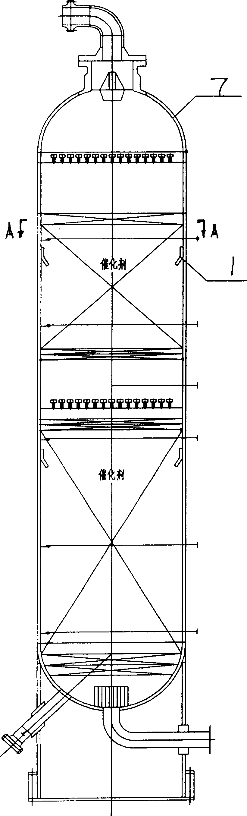
[0035] The application of two reactors in the "200,000 tons / year catalytic cracking gasoline hydro-upgrading unit". The design parameters of the two reactors are as follows:

[0036] One-stage reactor: operating pressure 2.55MPa, operating temperature 430°C, medium gasoline, hydrogen, specification size φ1400×19190×34.

[0037] Second stage reactor: operating pressure 2.65MPa, operating temperature 430°C, medium gasoline, hydrogen, specification size φ2400×16450×54.

[0038] The specific design steps are as follows:

[0039] According to the above parameters, it is calculated by the professional reaction of the process that the gas-liquid two-phase flow characteristics of the two reactors are basically the same during operation, the mass flow rate of the liquid phase flow is greater than that of the gas phase flow, and the flow rate between each bed of the catalyst The gas-liquid two-phase flow velocity is small, and the liquid phase flow ρv 2 =210~260kg / (m.s 2 ), gas phas...


PUM


Abstract

A technology for eliminating the wall flow of hydrogenating reactor to increase the output rate of reaction and its equipment are disclosed. A conic baffle disc whose diameter is the 3-7% of the internal diameter of reactor is installed above the catalyst bed in reactor in coaxial mode. The conic ring disc is fixed to the baffle cylinder by the connecting plate of fix regulating mechanism. Said baffle cylinder is fixed to inner wall of reactor. A sealing structure is arranged to external surface of said baffle cylinder.

Description

Technical field: [0001] The invention relates to the technical field of various hydrogenation reactors in petrochemical and other devices, and specifically relates to a hydrogenation reactor wall-free flow process and a device thereof. At the same time, it is also applicable to other reaction equipment with similar working conditions. It is an improvement on the structure of the original hydrogenation reactor to achieve the effect of increasing the reaction yield. Background technique: [0002] The reactor is the equipment that completes the chemical reaction process of two or more media, and is the core equipment in petrochemical and other equipment. Normally, reactants such as gas and liquid in the reactor pass through the fixed catalyst bed in a flowing state to complete the reaction process, and the gas and liquid flow in opposite directions, and the catalyst is still. The uniform flow of the reaction medium is the key to ensure the full and complete reaction, and it is...

Claims


Application Information

Patent Timeline
IPC IPC(8): B01J8/04
Inventor 李柏杜喜研崔云海陈福利王易萍栾海林
Owner 中国寰球工程有限公司辽宁分公司
Why Eureka
Try Eureka