Integrated wave filter for high temperature hyperconductive band-stop and band-pass
A technology of band-stop filter and band-pass filter, applied in waveguide devices, electrical components, circuits, etc. Difficult design and other issues to achieve good out-of-band suppression, narrow passband, and reduced volume and weight
- Summary
- Abstract
- Description
- Claims
- Application Information
AI Technical Summary
Problems solved by technology
Method used
Image
Examples
Embodiment 1
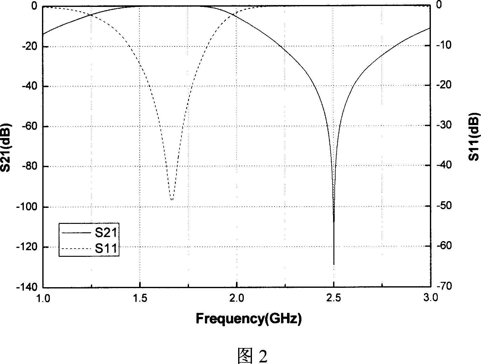
[0031] To design a high-temperature superconducting integrated filter bank, the central frequency of the passband is required to be f 1 =1715MHz, bandwidth Δf=15MHz, at f 2 = Around 2.5GHz, the impedance should be above -90dB.
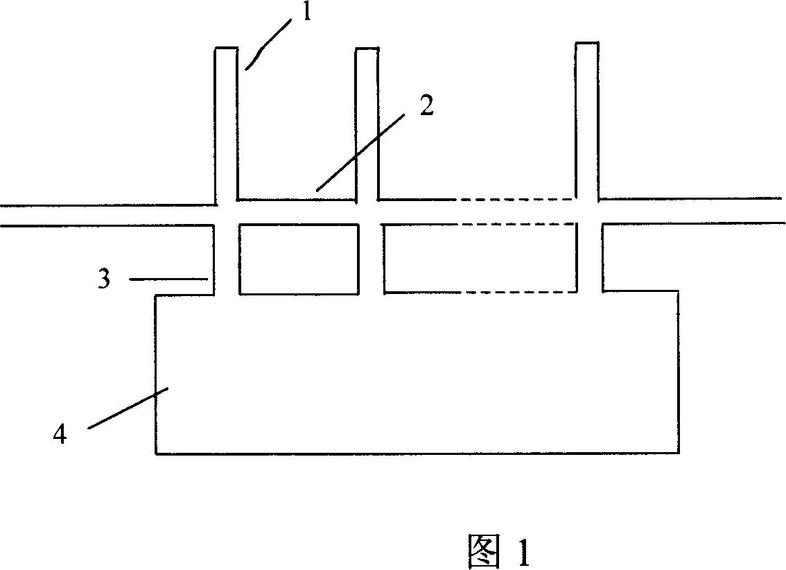
[0032] Design of high temperature superconducting bandpass filter: select the quasi-elliptic function model, and use related programs to obtain its theoretical curve (as shown in Figure 4) and related coupling parameters. Choose a hairpin-type zigzag resonator with a length of approx. (ε is the dielectric constant of the substrate). Use Sonnet software to simulate the resonator to obtain its simulation frequency, modify the length of the broken line of the resonator until the simulation frequency of the resonator is f 1 =1715MHz.
[0033] Arrange 8 such resonators in a certain order to form a quasi-elliptic bandpass filter. The coupling parameters between the resonators are as close as possible to the theoretical values through simulation. The...
Embodiment 2
[0037] The design requirements are the same as those in Example 1. The Chebyshev function model is selected for the high-temperature superconducting bandpass filter, and its theoretical curve (as shown in FIG. 9 ) and related coupling parameters are obtained by using related programs. Choose a clip-type broken-line resonator, and make the simulation frequency of the resonator f by simulation 1 =1715MHz. Arrange 8 such resonators in a straight line to form a Chebyshev-type bandpass filter, and through the method in Example 1, integrate it with the bandstop filter described in Example 1 to obtain the Design diagram of integrated filter with band-stop and Chebyshev-type band-pass.
Embodiment 3
[0039] The result designed in Example 1 is made into a photolithography template, the high-temperature superconducting double-sided film material used is YBCO, and the dielectric substrate is LaAlO 3 , the thickness of the substrate is 0.5mm, and the thickness of the superconducting film is about 0.6-0.7nm. The high temperature superconducting thin film is subjected to photolithography by a conventional method, and after the photolithographic mask on the surface of the high temperature superconducting thin film is formed, it is dry-etched by an ion etching machine. A high temperature superconducting filter can be obtained by cutting the dry-etched high temperature superconducting thin film into a required size with a semiconductor dicing machine and cleaning it.
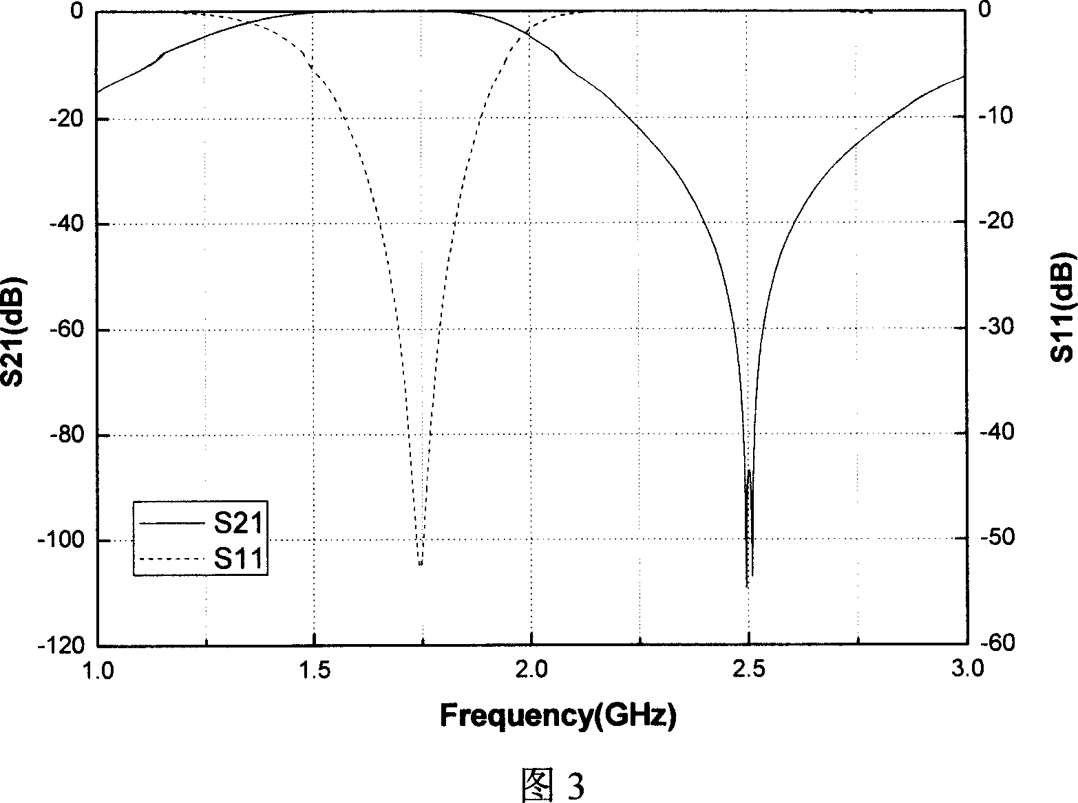
[0040] Figure 11 and Figure 12 are the actual measurement results of the integrated filter at 77K. Figure 11 shows the bandpass characteristics, the in-band differential loss is only 0.1-0.2dB, the out-of-band impeda...
PUM
| Property | Measurement | Unit |
|---|---|---|
| Thickness | aaaaa | aaaaa |
| Line width | aaaaa | aaaaa |
Abstract
Description
Claims
Application Information
 - R&D
- Intellectual Property
- Life Sciences
- Materials
- Tech Scout
- Unparalleled Data Quality
- Higher Quality Content
- 60% Fewer Hallucinations
Browse by: Latest US Patents, China's latest patents, Technical Efficacy Thesaurus, Application Domain, Technology Topic, Popular Technical Reports.
© 2025 PatSnap. All rights reserved.Legal|Privacy policy|Modern Slavery Act Transparency Statement|Sitemap|About US| Contact US: help@patsnap.com


